Information injection-pump assembly
ZEXEL
106871-3450
1068713450
HINO
220003591A
220003591a

Rating:
Cross reference number
ZEXEL
106871-3450
1068713450
HINO
220003591A
220003591a
Zexel num
Bosch num
Firm num
Name
Calibration Data:
Adjustment conditions
Test oil
1404 Test oil ISO4113 or {SAEJ967d}
1404 Test oil ISO4113 or {SAEJ967d}
Test oil temperature
degC
40
40
45
Nozzle and nozzle holder
105780-8140
Bosch type code
EF8511/9A
Nozzle
105780-0000
Bosch type code
DN12SD12T
Nozzle holder
105780-2080
Bosch type code
EF8511/9
Opening pressure
MPa
17.2
Opening pressure
kgf/cm2
175
Injection pipe
Outer diameter - inner diameter - length (mm) mm 8-3-600
Outer diameter - inner diameter - length (mm) mm 8-3-600
Overflow valve
134424-0820
Overflow valve opening pressure
kPa
127.5
118
137
Overflow valve opening pressure
kgf/cm2
1.3
1.2
1.4
Tester oil delivery pressure
kPa
157
157
157
Tester oil delivery pressure
kgf/cm2
1.6
1.6
1.6
Direction of rotation (viewed from drive side)
Right R
Right R
Injection timing adjustment
Direction of rotation (viewed from drive side)
Right R
Right R
Injection order
1-8-6-2-
7-5-4-3
Pre-stroke
mm
3.9
3.84
3.9
Beginning of injection position
Drive side NO.1
Drive side NO.1
Difference between angles 1
Cal 1-8 deg. 45 44.75 45.25
Cal 1-8 deg. 45 44.75 45.25
Difference between angles 2
Cal 1-6 deg. 90 89.75 90.25
Cal 1-6 deg. 90 89.75 90.25
Difference between angles 3
Cyl.1-2 deg. 135 134.75 135.25
Cyl.1-2 deg. 135 134.75 135.25
Difference between angles 4
Cal 1-7 deg. 180 179.75 180.25
Cal 1-7 deg. 180 179.75 180.25
Difference between angles 5
Cal 1-5 deg. 225 224.75 225.25
Cal 1-5 deg. 225 224.75 225.25
Difference between angles 6
Cal 1-4 deg. 270 269.75 270.25
Cal 1-4 deg. 270 269.75 270.25
Difference between angles 7
Cal 1-3 deg. 315 314.75 315.25
Cal 1-3 deg. 315 314.75 315.25
Injection quantity adjustment
Adjusting point
A
Rack position
10.2
Pump speed
r/min
500
500
500
Average injection quantity
mm3/st.
135.3
132.3
138.3
Max. variation between cylinders
%
0
-4
4
Fixing the lever
*
Boost pressure
kPa
20
20
Boost pressure
mmHg
150
150
Injection quantity adjustment_02
Adjusting point
B
Rack position
10.9
Pump speed
r/min
700
700
700
Average injection quantity
mm3/st.
155.8
153.8
157.8
Max. variation between cylinders
%
0
-2
2
Basic
*
Fixing the lever
*
Boost pressure
kPa
20
20
Boost pressure
mmHg
150
150
Injection quantity adjustment_03
Adjusting point
C
Rack position
10.9
Pump speed
r/min
1100
1100
1100
Average injection quantity
mm3/st.
162.9
159.9
165.9
Max. variation between cylinders
%
0
-4
4
Fixing the lever
*
Boost pressure
kPa
20
20
Boost pressure
mmHg
150
150
Injection quantity adjustment_04
Adjusting point
I
Rack position
6.5+-0.5
Pump speed
r/min
225
225
225
Average injection quantity
mm3/st.
17
14
20
Max. variation between cylinders
%
0
-15
15
Fixing the rack
*
Boost pressure
kPa
0
0
0
Boost pressure
mmHg
0
0
0
Injection quantity adjustment_05
Adjusting point
D
Rack position
-
Pump speed
r/min
100
100
100
Average injection quantity
mm3/st.
128
128
Fixing the lever
*
Boost pressure
kPa
0
0
0
Boost pressure
mmHg
0
0
0
Injection quantity adjustment_06
Adjusting point
E
Rack position
-
Pump speed
r/min
100
100
100
Average injection quantity
mm3/st.
140
140
160
Fixing the lever
*
Boost pressure
kPa
20
20
Boost pressure
mmHg
150
150
Rack limit
*
Boost compensator adjustment
Pump speed
r/min
500
500
500
Rack position
9.2
Boost pressure
kPa
4
1.3
6.7
Boost pressure
mmHg
30
10
50
Boost compensator adjustment_02
Pump speed
r/min
500
500
500
Rack position
10.2
Boost pressure
kPa
10
10
12.7
Boost pressure
mmHg
75
55
95
Timer adjustment
Pump speed
r/min
925
Advance angle
deg.
0.5
Timer adjustment_02
Pump speed
r/min
950
Advance angle
deg.
0.6
0.1
1.1
Timer adjustment_03
Pump speed
r/min
1000
Advance angle
deg.
25
24.5
25.5
Remarks
Finish
Finish
Test data Ex:
Governor adjustment
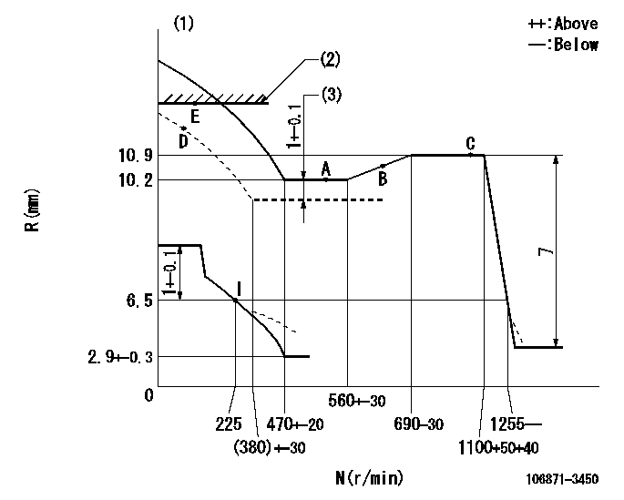
N:Pump speed
R:Rack position (mm)
(1)Beginning of damper spring operation: DL
(2)RACK LIMIT
(3)Boost compensator stroke (at N = N1)
----------
DL=4.9-0.2mm N1=500r/min
----------
----------
DL=4.9-0.2mm N1=500r/min
----------
Speed control lever angle

F:Full speed
----------
----------
a=17deg+-5deg
----------
----------
a=17deg+-5deg
0000000901
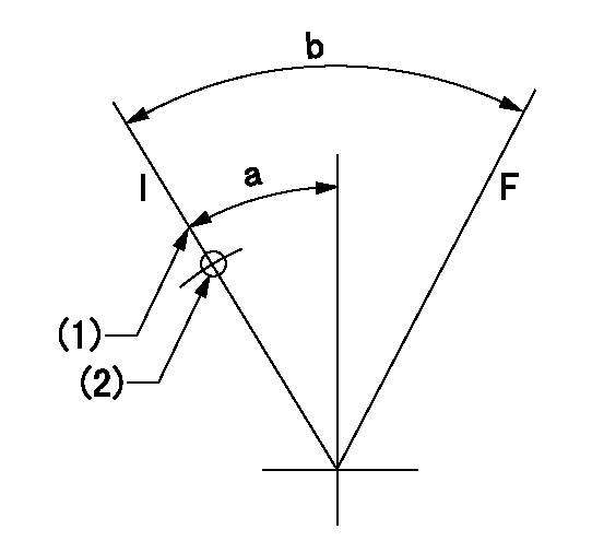
F:Full load
I:Idle
(1)Stopper bolt setting
(2)R = center of hole above aa
----------
aa=50mm
----------
a=20deg+-5deg b=39deg+-3deg
----------
aa=50mm
----------
a=20deg+-5deg b=39deg+-3deg
Stop lever angle
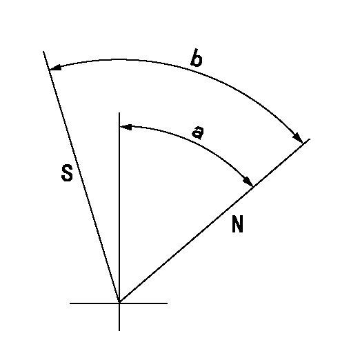
N:Pump normal
S:Stop the pump.
----------
----------
a=39deg+-5deg b=48.5deg+-3deg
----------
----------
a=39deg+-5deg b=48.5deg+-3deg
0000001501 GOVERNOR TORQUE CONTROL
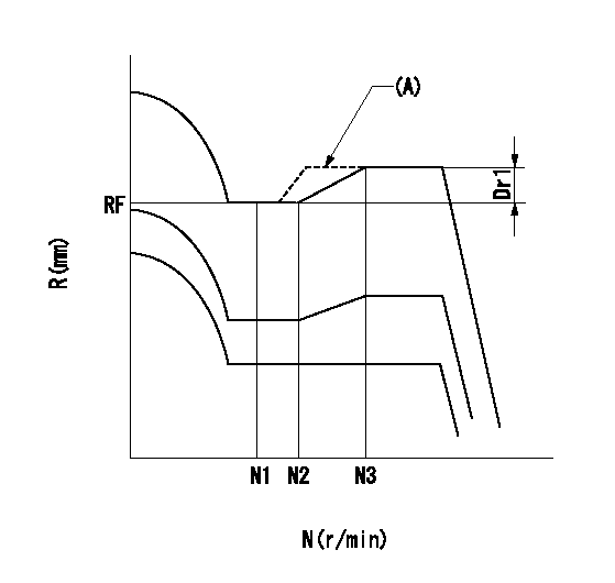
Dr:Torque control stroke
(A): Without torque control spring capsule
1. Adjustment procedures
(1)Procedure is the same as that for the RFD (former type), except that the positive torque control stroke must be determined at the full lever setting.
2. Procedures for adjustment
(1)Remove the torque control spring capsule.
(2)Operate the pump at approximately N1. (End of idling spring operation < N1.)
(3)Tilt the lever to the full side.
(4)Set so that R = RF.
(5)Increase the speed by pushing in the screw (attached to the bracket on the rear of the tension lever) through the adjusting window.
(6)Adjust so that the torque control stroke Dr1 can be obtained.
(7)Align N2 and N3 with the torque control spring capsule.
----------
N1=500r/min N2=560+-30r/min N3=690-30r/min RF=10.2mm Dr1=0.7mm
----------
----------
N1=500r/min N2=560+-30r/min N3=690-30r/min RF=10.2mm Dr1=0.7mm
----------
Information:
Table 2
Specifications for Valve Opening Pressure
Nozzle Assembly Valve Opening Pressure
1W-5829
10300 to 17690 kPa (1500 to 2505 psi)
4W-1819
4W-8483
7E-3969
7N-0449
7W-3710
7W-8043
9N-3979
101-0060
115-3354
122-9007
9L-7883
16560 to 17990 kPa (2400 to 2600 psi)
9L-9263
9N-2366
9L-6969
13090 to 19900 kPa (1900 2900 psi)
9N-3299
9N-3700 If the fuel nozzle is not within specifications, stop the test and do not use the nozzle.Check for Tip Leakage
Close the gauge protector valve (0 to 40,000 kPa (0 to 5,800 psi) gauge).
Flush the fuel nozzle that is being tested by pumping the tester for 3 full strokes.
Open the gauge protector valve (0 to 40,000 kPa (0 to 5,800 psi) gauge).
Use a clean cloth to dry the tip and the body of the fuel injector. All test fluid should be wiped from the nozzle assembly.
A clean cloth should be wrapped around the top of the fuel nozzle in order to absorb any internal return leakage.
Calculate the test pressure that will be used for the tip leakage test.Use the fuel nozzle's valve opening pressure, that has been previously recorded, in order to calculate the test pressure for the nozzle that is being tested.
Subtract a value of 1875 kPa (275 psi) from the valve opening pressure that was previously obtained.
Record the result of the calculation as the test pressure that will be used for the tip leakage test.
Slowly apply the test pressure, that has been calculated in Step 6, to the fuel nozzle.
Close the pump isolator valve.
Hold this test pressure for 10 seconds.
Count the number of drops of test fluid that drips from the nozzle during the duration of the test. Open the pump isolator valve in order to release the pressure on the fuel nozzle when the test is completed.Refer to the information that is provided in Table 3 in order to evaluate the results of the test.Note: Ensure that any test fluid that collects on the tip of the fuel nozzle is not fluid leakage from the test fixture.
Table 3
Specifications for Tip Leakage
(Leakage within 15 seconds after the test pressure is applied to the nozzle.)
Nozzle Assembly Maximum Leakage
1W-5829 20 drops (1)
4W-1819
4W-8483
7E-3969
7N-0449
7W-3710
7W-8043
9N-3979
101-0060
115-3354
122-9007
9L-7883 3 drops (1)
9L-9263
9N-2366
9L-6969 30 drops (1)
9N-3299
9N-3700
( 1 ) No minimum specificationIf the tip leakage for the fuel nozzle is not within specifications, stop the test and do not use the fuel nozzle.Test the Fuel Nozzle for Plugged Orifices
Illustration 2 g00923165
Spray patterns for pencil type fuel nozzles.
Close the gauge protector valve (0 to 40,000 kPa (0 to 5,800 psi) gauge).
Rapidly increase the pressure on the fuel nozzle until fluid sprays from the tip of the fuel nozzle.Note: For this test, each full