Information injection-pump assembly
ZEXEL
106871-3290
1068713290
HINO
220003471C
220003471c
Rating:
Service parts 106871-3290 INJECTION-PUMP ASSEMBLY:
1.
_
7.
COUPLING PLATE
8.
_
9.
_
11.
Nozzle and Holder
23600-1480
12.
Open Pre:MPa(Kqf/cm2)
21.6{220}
15.
NOZZLE SET
Include in #1:
106871-3290
as INJECTION-PUMP ASSEMBLY
Cross reference number
ZEXEL
106871-3290
1068713290
HINO
220003471C
220003471c
Zexel num
Bosch num
Firm num
Name
Calibration Data:
Adjustment conditions
Test oil
1404 Test oil ISO4113 or {SAEJ967d}
1404 Test oil ISO4113 or {SAEJ967d}
Test oil temperature
degC
40
40
45
Nozzle and nozzle holder
105780-8140
Bosch type code
EF8511/9A
Nozzle
105780-0000
Bosch type code
DN12SD12T
Nozzle holder
105780-2080
Bosch type code
EF8511/9
Opening pressure
MPa
17.2
Opening pressure
kgf/cm2
175
Injection pipe
Outer diameter - inner diameter - length (mm) mm 8-3-600
Outer diameter - inner diameter - length (mm) mm 8-3-600
Overflow valve
134424-0820
Overflow valve opening pressure
kPa
127.5
118
137
Overflow valve opening pressure
kgf/cm2
1.3
1.2
1.4
Tester oil delivery pressure
kPa
157
157
157
Tester oil delivery pressure
kgf/cm2
1.6
1.6
1.6
Direction of rotation (viewed from drive side)
Right R
Right R
Injection timing adjustment
Direction of rotation (viewed from drive side)
Right R
Right R
Injection order
1-8-6-2-
7-5-4-3
Pre-stroke
mm
3.9
3.84
3.9
Beginning of injection position
Drive side NO.1
Drive side NO.1
Difference between angles 1
Cal 1-8 deg. 45 44.75 45.25
Cal 1-8 deg. 45 44.75 45.25
Difference between angles 2
Cal 1-6 deg. 90 89.75 90.25
Cal 1-6 deg. 90 89.75 90.25
Difference between angles 3
Cyl.1-2 deg. 135 134.75 135.25
Cyl.1-2 deg. 135 134.75 135.25
Difference between angles 4
Cal 1-7 deg. 180 179.75 180.25
Cal 1-7 deg. 180 179.75 180.25
Difference between angles 5
Cal 1-5 deg. 225 224.75 225.25
Cal 1-5 deg. 225 224.75 225.25
Difference between angles 6
Cal 1-4 deg. 270 269.75 270.25
Cal 1-4 deg. 270 269.75 270.25
Difference between angles 7
Cal 1-3 deg. 315 314.75 315.25
Cal 1-3 deg. 315 314.75 315.25
Injection quantity adjustment
Adjusting point
A
Rack position
9.5
Pump speed
r/min
500
500
500
Average injection quantity
mm3/st.
128.7
125.7
131.7
Max. variation between cylinders
%
0
-4
4
Fixing the lever
*
Boost pressure
kPa
32
32
Boost pressure
mmHg
240
240
Injection quantity adjustment_02
Adjusting point
B
Rack position
10.1
Pump speed
r/min
700
700
700
Average injection quantity
mm3/st.
146
144
148
Max. variation between cylinders
%
0
-2
2
Basic
*
Fixing the lever
*
Boost pressure
kPa
32
32
Boost pressure
mmHg
240
240
Injection quantity adjustment_03
Adjusting point
C
Rack position
10.4
Pump speed
r/min
1100
1100
1100
Average injection quantity
mm3/st.
158.3
155.3
161.3
Max. variation between cylinders
%
0
-4
4
Fixing the lever
*
Boost pressure
kPa
32
32
Boost pressure
mmHg
240
240
Injection quantity adjustment_04
Adjusting point
D
Rack position
6.2+-0.5
Pump speed
r/min
225
225
225
Average injection quantity
mm3/st.
13.3
10.3
16.3
Max. variation between cylinders
%
0
-1.5
1.5
Fixing the rack
*
Boost pressure
kPa
0
0
0
Boost pressure
mmHg
0
0
0
Injection quantity adjustment_05
Adjusting point
E
Rack position
-
Pump speed
r/min
100
100
100
Average injection quantity
mm3/st.
121
121
Fixing the lever
*
Boost pressure
kPa
0
0
0
Boost pressure
mmHg
0
0
0
Injection quantity adjustment_06
Adjusting point
H
Rack position
-
Pump speed
r/min
100
100
100
Average injection quantity
mm3/st.
137.3
137.3
157.3
Fixing the lever
*
Boost pressure
kPa
32
32
Boost pressure
mmHg
240
240
Rack limit
*
Boost compensator adjustment
Pump speed
r/min
500
500
500
Rack position
8.7
Boost pressure
kPa
4
1.3
6.7
Boost pressure
mmHg
30
10
50
Boost compensator adjustment_02
Pump speed
r/min
500
500
500
Rack position
9.5
Boost pressure
kPa
9.3
6.6
12
Boost pressure
mmHg
70
50
90
Timer adjustment
Pump speed
r/min
925
Advance angle
deg.
0.3
Timer adjustment_02
Pump speed
r/min
950
Advance angle
deg.
1.1
Timer adjustment_03
Pump speed
r/min
1000
Advance angle
deg.
1.5
1.2
1.8
Remarks
Finish
Finish
Test data Ex:
Governor adjustment
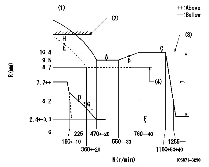
N:Pump speed
R:Rack position (mm)
(1)Beginning of damper spring operation: DL
(2)RACK LIMIT: RAL
(3)Boost pressure: not less than BP1
(4)Boost pressure: not less than BP2
----------
DL=4.6-0.2mm RAL=(11.6)mm BP1=240mmHg BP2=0mmHg
----------
----------
DL=4.6-0.2mm RAL=(11.6)mm BP1=240mmHg BP2=0mmHg
----------
Speed control lever angle

F:Full speed
----------
----------
a=15deg+-5deg
----------
----------
a=15deg+-5deg
0000000901
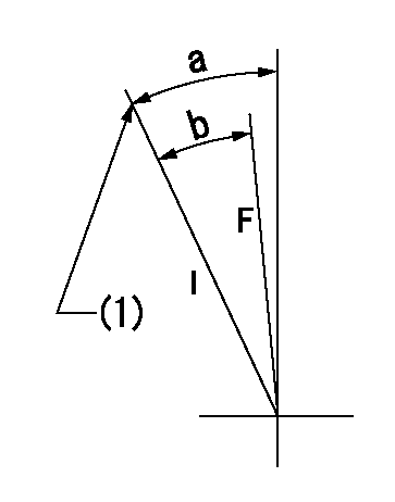
F:Full load
I:Idle
(1)Stopper bolt setting
----------
----------
a=29deg+-5deg b=28deg+-3deg
----------
----------
a=29deg+-5deg b=28deg+-3deg
Stop lever angle
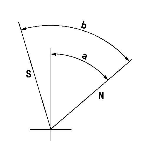
N:Pump normal
S:Stop the pump.
----------
----------
a=39deg+-5deg b=48.5deg+-3deg
----------
----------
a=39deg+-5deg b=48.5deg+-3deg
Information:
Introduction
The problem that is identified below does not have a known permanent solution. Until a permanent solution is known, use the solution that is identified below.Problem
Illustration 1 g01955898
Typical exampleThere have been a number of remanufactured 3054C engines that were assembled with a loose 111-3422 Nut (1) for the gear for the injection pump (2). This nut has only received an initial torque of 25 N m (18 lb ft). A second torque of 88 N m (65 lb ft) is required. Without this required torque, the timing of the engine may be affected.The remanufactured part numbers for the engine and serial numbers that have been identified with the loose nut for the fuel injection pump gear are listed in table 1.
Table 1
Part Number of the Engine Arrangement Engine Serial Number
10R-5995 54E09007
54E09008
54E09009
54E09010
54E09011
54E09012
54E09013
54E09063
54E09064
54E09065
54E09066
54E09071
54E09073
54E09074
54E09075
10R-5996 54E09055
54E09056
54E09057
10R-5998 54E09039
54E09058
10R-8791 54E09022
54E09023
54E09024
54E09025
54E09026
54E09028 Solution
The nut that secures the fuel injection pump gear requires a second torque of 88 N m (65 lb ft) prior to engine operation. Refer to Disassembly and Assembly, "Front Cover - Remove and Install" for the correct procedure to remove the front cover. Refer to Disassembly and Assembly, "Fuel Injection Pump - Install" for the correct procedure to tighten the nut.