Information injection-pump assembly
ZEXEL
106871-3230
1068713230
HINO
220002154B
220002154b
Rating:
Service parts 106871-3230 INJECTION-PUMP ASSEMBLY:
1.
_
7.
COUPLING PLATE
8.
_
9.
_
11.
Nozzle and Holder
23600-1212
12.
Open Pre:MPa(Kqf/cm2)
21.6{220}
15.
NOZZLE SET
Include in #1:
106871-3230
as INJECTION-PUMP ASSEMBLY
Cross reference number
ZEXEL
106871-3230
1068713230
HINO
220002154B
220002154b
Zexel num
Bosch num
Firm num
Name
Calibration Data:
Adjustment conditions
Test oil
1404 Test oil ISO4113 or {SAEJ967d}
1404 Test oil ISO4113 or {SAEJ967d}
Test oil temperature
degC
40
40
45
Nozzle and nozzle holder
105780-8140
Bosch type code
EF8511/9A
Nozzle
105780-0000
Bosch type code
DN12SD12T
Nozzle holder
105780-2080
Bosch type code
EF8511/9
Opening pressure
MPa
17.2
Opening pressure
kgf/cm2
175
Injection pipe
Outer diameter - inner diameter - length (mm) mm 8-3-600
Outer diameter - inner diameter - length (mm) mm 8-3-600
Overflow valve
134424-1020
Overflow valve opening pressure
kPa
127
107
147
Overflow valve opening pressure
kgf/cm2
1.3
1.1
1.5
Tester oil delivery pressure
kPa
157
157
157
Tester oil delivery pressure
kgf/cm2
1.6
1.6
1.6
Direction of rotation (viewed from drive side)
Right R
Right R
Injection timing adjustment
Direction of rotation (viewed from drive side)
Right R
Right R
Injection order
1-8-6-2-
7-5-4-3
Pre-stroke
mm
4
3.94
4
Beginning of injection position
Drive side NO.1
Drive side NO.1
Difference between angles 1
Cal 1-8 deg. 45 44.75 45.25
Cal 1-8 deg. 45 44.75 45.25
Difference between angles 2
Cal 1-6 deg. 90 89.75 90.25
Cal 1-6 deg. 90 89.75 90.25
Difference between angles 3
Cyl.1-2 deg. 135 134.75 135.25
Cyl.1-2 deg. 135 134.75 135.25
Difference between angles 4
Cal 1-7 deg. 180 179.75 180.25
Cal 1-7 deg. 180 179.75 180.25
Difference between angles 5
Cal 1-5 deg. 225 224.75 225.25
Cal 1-5 deg. 225 224.75 225.25
Difference between angles 6
Cal 1-4 deg. 270 269.75 270.25
Cal 1-4 deg. 270 269.75 270.25
Difference between angles 7
Cal 1-3 deg. 315 314.75 315.25
Cal 1-3 deg. 315 314.75 315.25
Injection quantity adjustment
Adjusting point
A
Rack position
9.3
Pump speed
r/min
500
500
500
Average injection quantity
mm3/st.
115.2
112.2
118.2
Max. variation between cylinders
%
0
-4
4
Fixing the lever
*
Injection quantity adjustment_02
Adjusting point
B
Rack position
9.45
Pump speed
r/min
700
700
700
Average injection quantity
mm3/st.
116.6
114.6
118.6
Max. variation between cylinders
%
0
-2
2
Basic
*
Fixing the lever
*
Injection quantity adjustment_03
Adjusting point
C
Rack position
10.1
Pump speed
r/min
1200
1200
1200
Average injection quantity
mm3/st.
139
136
142
Max. variation between cylinders
%
0
-4
4
Fixing the lever
*
Injection quantity adjustment_04
Adjusting point
D
Rack position
6.4+-0.5
Pump speed
r/min
225
225
225
Average injection quantity
mm3/st.
13.7
10.7
16.7
Max. variation between cylinders
%
0
-15
15
Fixing the rack
*
Injection quantity adjustment_05
Adjusting point
E
Rack position
-
Pump speed
r/min
50
50
50
Average injection quantity
mm3/st.
130
130
150
Fixing the lever
*
Remarks
After startup boost setting
After startup boost setting
Injection quantity adjustment_06
Adjusting point
F
Rack position
-
Pump speed
r/min
1000
1000
1000
Average injection quantity
mm3/st.
0
0
0
Fixing the lever
*
Timer adjustment
Pump speed
r/min
950
Advance angle
deg.
0.4
Timer adjustment_02
Pump speed
r/min
1000
Advance angle
deg.
0.7
0.2
1.2
Timer adjustment_03
Pump speed
r/min
1050
Advance angle
deg.
1.6
1.1
2.1
Timer adjustment_04
Pump speed
r/min
1125
Advance angle
deg.
3
2.7
3.3
Remarks
Finish
Finish
Test data Ex:
Governor adjustment
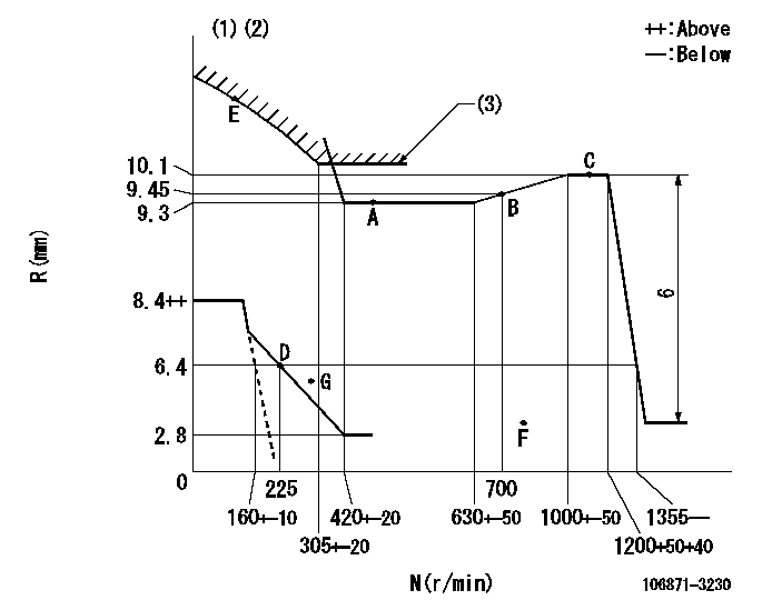
N:Pump speed
R:Rack position (mm)
(1)Beginning of damper spring operation: DL
(2)Set idle at point G (N = N1, R = R1) and confirm that the fuel injection quantity at point F (N = N2) does not exceed Q1.
(3)Excess fuel setting for starting: SXL
----------
DL=5.4-0.2mm N1=300r/min R1=5.4mm N2=1000r/min Q1=0mm3/st SXL=10.1+0.2mm
----------
----------
DL=5.4-0.2mm N1=300r/min R1=5.4mm N2=1000r/min Q1=0mm3/st SXL=10.1+0.2mm
----------
Speed control lever angle

F:Full speed
----------
----------
a=4deg+-5deg
----------
----------
a=4deg+-5deg
0000000901
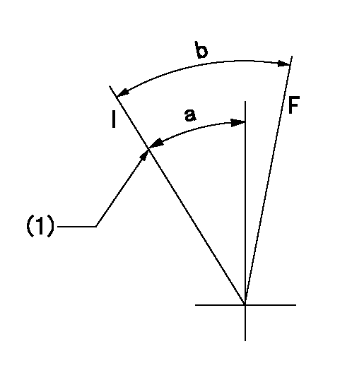
F:Full load
I:Idle
(1)Stopper bolt setting
----------
----------
a=34deg+-5deg b=35deg+-3deg
----------
----------
a=34deg+-5deg b=35deg+-3deg
Stop lever angle

N:Pump normal
S:Stop the pump.
----------
----------
a=15deg+-5deg b=64deg+-5deg
----------
----------
a=15deg+-5deg b=64deg+-5deg
0000001501 MICRO SWITCH
Switch adjustment
Adjust the bolt so that the lower lever position is obtained when the switch is turned ON.
(1)Speed N1
(2)Rack position Ra
----------
N1=325-25r/min Ra=6.4mm
----------
----------
N1=325-25r/min Ra=6.4mm
----------
Information:
Introduction
This document provides information about fuel degradation, which can cause a flow restriction of fuel through the fuel system and premature plugging of the filters. These guidelines should be used to guide service personnel in the use of fuels within diesel engines and covers recognized tests in identifying degredated fuels and best practices in storing fuels.This document can be used as a guide, but it does not provide all the information on all practices and procedures for degraded fuels. This document does not provide all the information for best practices for storing and handling fuels. Refer to Caterpillar Commercial Diesel Engine Fluids Recommendations, SEBU6251 for more information.The Thermal Stability and Oxidation Stability of Fuel
Diesel fuels can deteriorate rapidly for a variety of reasons. When the fuel is stressed and stored for long intervals, degradation and oxidation can occur. Degradation and oxidation are complex chemical changes. These changes lead to deposits or sediment from certain hydrocarbons and traces of naturally occurring nitrogen and sulfur containing compounds in the fuel. Fuel composition and environmental factors influences the process.Diesel fuel is being used as a coolant for high pressure fuel injection systems with high temperature fuel wetted walls. This can stress the fuel in the fuel system. The thermal stress and an increase in recirculation fuel temperature is often responsible for fuel degradation and the formation of gums, resins and sediment, which can cause fuel flow restriction through fuel filters and fuel injection systems.Certain products are often left with the fuel in the fuel system for long periods. This exposes the fuel to oxygen. Complex reactions between the oxygen and the fuel components can generate fuel particulates. The particulates in the fuel system can turn into the sludge that is found in fuel tanks, fuel lines and the fuel filters. This will deteriorate the performance of the fuel system. Degradation also leads to a plugged fuel filter, a restriction to the fuel line and deposit formation in the fuel injection nozzle.Biodiesel and blends of biodiesel have poor thermal stability and oxidation stability compared to petroleum distillate diesel fuels. The use of these biodiesels and blends of biodiesel can accelerate the problems that are addressed in this Special Instruction. Using biodiesel blends above the maximum level approved for the engine is not recommended.Thermal and oxidative degradation of diesel fuel can result in a darkening of fuel color. Fuel color is not necessarily an indication of excessive degradation that will lead to the problems outlined in thisSpecial Instruction, but can be an indicator or degradation If concerns arise about the stability of darkened fuel, the thermal oxidation and oxidative stability tests should be run to confirm actual degradation.Thermal Oxidation Stability
Caterpillar recommends the use of the Accelerated Fuel Oil Stability Test (ASTM D6468). This is a test method that determines the instability of a fuel subjected to a thermal degradation process. This test exposes the fuel to actual operating conditions when the fuel cools the injectors during the engine operation.The test is performed by