Information injection-pump assembly
ZEXEL
106871-3210
1068713210
HINO
220001306A
220001306a
Rating:
Service parts 106871-3210 INJECTION-PUMP ASSEMBLY:
1.
_
7.
COUPLING PLATE
8.
_
9.
_
11.
Nozzle and Holder
23600-1212
12.
Open Pre:MPa(Kqf/cm2)
21.6{220}
15.
NOZZLE SET
Include in #1:
106871-3210
as INJECTION-PUMP ASSEMBLY
Cross reference number
ZEXEL
106871-3210
1068713210
HINO
220001306A
220001306a
Zexel num
Bosch num
Firm num
Name
106871-3210
220001306A HINO
INJECTION-PUMP ASSEMBLY
EF700 * K
EF700 * K
Calibration Data:
Adjustment conditions
Test oil
1404 Test oil ISO4113 or {SAEJ967d}
1404 Test oil ISO4113 or {SAEJ967d}
Test oil temperature
degC
40
40
45
Nozzle and nozzle holder
105780-8140
Bosch type code
EF8511/9A
Nozzle
105780-0000
Bosch type code
DN12SD12T
Nozzle holder
105780-2080
Bosch type code
EF8511/9
Opening pressure
MPa
17.2
Opening pressure
kgf/cm2
175
Injection pipe
Outer diameter - inner diameter - length (mm) mm 8-3-600
Outer diameter - inner diameter - length (mm) mm 8-3-600
Overflow valve
134424-0820
Overflow valve opening pressure
kPa
127
107
147
Overflow valve opening pressure
kgf/cm2
1.3
1.1
1.5
Tester oil delivery pressure
kPa
157
157
157
Tester oil delivery pressure
kgf/cm2
1.6
1.6
1.6
Direction of rotation (viewed from drive side)
Right R
Right R
Injection timing adjustment
Direction of rotation (viewed from drive side)
Right R
Right R
Injection order
1-8-6-2-
7-5-4-3
Pre-stroke
mm
4
3.9
4
Beginning of injection position
Drive side NO.1
Drive side NO.1
Difference between angles 1
Cal 1-8 deg. 45 44.5 45.5
Cal 1-8 deg. 45 44.5 45.5
Difference between angles 2
Cal 1-6 deg. 90 89.5 90.5
Cal 1-6 deg. 90 89.5 90.5
Difference between angles 3
Cyl.1-2 deg. 135 134.5 135.5
Cyl.1-2 deg. 135 134.5 135.5
Difference between angles 4
Cal 1-7 deg. 180 179.5 180.5
Cal 1-7 deg. 180 179.5 180.5
Difference between angles 5
Cal 1-5 deg. 225 224.5 225.5
Cal 1-5 deg. 225 224.5 225.5
Difference between angles 6
Cal 1-4 deg. 270 269.5 270.5
Cal 1-4 deg. 270 269.5 270.5
Difference between angles 7
Cal 1-3 deg. 315 314.5 315.5
Cal 1-3 deg. 315 314.5 315.5
Injection quantity adjustment
Adjusting point
A
Rack position
9.3
Pump speed
r/min
500
500
500
Average injection quantity
mm3/st.
114.6
111.6
117.6
Max. variation between cylinders
%
0
-4
4
Fixing the lever
*
Injection quantity adjustment_02
Adjusting point
B
Rack position
9.4
Pump speed
r/min
700
700
700
Average injection quantity
mm3/st.
115
113
117
Max. variation between cylinders
%
0
-2
2
Basic
*
Fixing the lever
*
Injection quantity adjustment_03
Adjusting point
C
Rack position
10.2
Pump speed
r/min
1200
1200
1200
Average injection quantity
mm3/st.
141.2
138.2
144.2
Max. variation between cylinders
%
0
-4
4
Fixing the lever
*
Injection quantity adjustment_04
Adjusting point
D
Rack position
6.4+-0.5
Pump speed
r/min
225
225
225
Average injection quantity
mm3/st.
13.7
10.7
16.7
Max. variation between cylinders
%
0
-15
15
Fixing the rack
*
Injection quantity adjustment_05
Adjusting point
E
Rack position
-
Pump speed
r/min
50
50
50
Average injection quantity
mm3/st.
122
112
132
Fixing the lever
*
Remarks
After startup boost setting
After startup boost setting
Injection quantity adjustment_06
Adjusting point
F
Rack position
-
Pump speed
r/min
1000
1000
1000
Average injection quantity
mm3/st.
0
Fixing the lever
*
Timer adjustment
Pump speed
r/min
950+-50
Advance angle
deg.
0
0
0
Remarks
Start
Start
Timer adjustment_02
Pump speed
r/min
1100
Advance angle
deg.
1
0.5
1.5
Timer adjustment_03
Pump speed
r/min
1200
Advance angle
deg.
2
1.5
2.5
Remarks
Finish
Finish
Test data Ex:
Governor adjustment
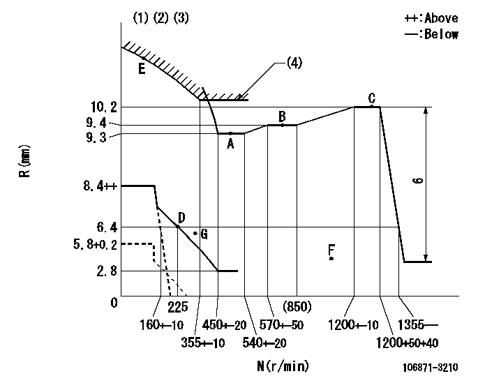
N:Pump speed
R:Rack position (mm)
(1)Beginning of damper spring operation: DL
(2)Set idle at point G (N = N1, R = R1) and confirm that the fuel injection quantity at point F (N = N2) does not exceed Q1.
(3)Set the load lever's stop position so that R = aa (N = 0).
(4)Excess fuel setting for starting: SXL
----------
DL=5.4-0.2mm N1=300r/min R1=5.4mm N2=1000r/min Q1=0mm3/st aa=5.8+0.2mm SXL=10.2+0.2mm
----------
----------
DL=5.4-0.2mm N1=300r/min R1=5.4mm N2=1000r/min Q1=0mm3/st aa=5.8+0.2mm SXL=10.2+0.2mm
----------
Speed control lever angle

F:Full speed
----------
----------
a=4deg+-5deg
----------
----------
a=4deg+-5deg
0000000901
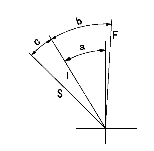
F:Full load
I:Idle
S:Stop
----------
----------
a=32deg+-5deg b=33deg+-3deg c=19deg+4deg-5deg
----------
----------
a=32deg+-5deg b=33deg+-3deg c=19deg+4deg-5deg
0000001501 MICRO SWITCH
Switch adjustment
Adjust the bolt so that the lower lever position is obtained when the switch is turned ON.
(1)Speed N1
(2)Rack position Ra
----------
N1=325-25r/min Ra=6.4mm
----------
----------
N1=325-25r/min Ra=6.4mm
----------
Information:
Illustration 4 g01621593
(4) The process of crimping has been improved in the location that is shown. The Fifth Improvement
The length of the bolts that secure the fuel transfer pump to the HEUI pump body have increased. The torques on the bolts that secure the transfer pump to the HEUI pump body have also increased in order to improve durability.
HEUI pumps that have been returned from the field have been inspected and broken bolts that connect the fuel transfer pump to the main HEUI pump were found.
The major symptom that is related to this issue is an oil leak between the fuel transfer pump and the HEUI pump.
The bolts that make this connection were lengthened as well as the torques were increased in order to provide a better connection.
This improvement was effective with the following part numbers: 319-0607, 319-0674, 319-0675, 319-0676, 319-0677, 319-0678, 319-0622, 319-0610 and 319-0680
Illustration 5 g01621594
(5) Location of the three bolts that have been lengthened and increased torques have been applied. Note: The applications that utilize an electric fuel transfer pump also have this improvement for the cover that goes in place of the mechanical fuel transfer pump.Note: Refer to Special Instruction , REHS3830 for the following items: parts information, installation of parts and torque procedures that are related to this improvement.All current remanufactured part numbers are being built with the latest improvements. A list of all the current new part numbers and the part numbers of the remanufactured equivalent can be seen below.
Table 1
Current New Part Numbers Remanufactured Equivalent
319-0607 -
319-0674 -
319-0675 10R7145
319-0676 10R7146
319-0677 10R7147
319-0678 10R7148
319-0622 -
319-0610 10R3044
319-0680 - Note: All part numbers that are referenced in this publication were current on 15 July 2008. Part numbers are subject to a change.
Table 2
New Part Numbers Serial Number Prefixes that Use the Part Numbers
319-0607 S/N:532, ; S/N:551, ; S/N:511, ; S/N:521, ; S/N:522, ; S/N:525, ; S/N:535, ; S/N:541, ; S/N:545, ; S/N:552, ; S/N:B3T, ; S/N:B9D, ; S/N:B9M, ; S/N:D9G
319-0674 S/N:C7D, ; S/N:C7P, ; S/N:C7Z, ; S/N:M7A
319-0675 S/N:HEP, ; S/N:BTM, ; S/N:CAP, ; S/N:CGZ, ; S/N:GAG, ; S/N:HAA, ; S/N:JAB, ; S/N:JCD, ; S/N:KDD, ; S/N:MCA, ; S/N:CYA, ; S/N:GKX, ; S/N:JNK, ; S/N:RBH, ; S/N:MKM, ; S/N:MSD, ; S/N:MSL, ; S/N:CEX, ; S/N:CEH, ; S/N:BCP, ; S/N:CLJ, ; S/N:AEM, ; S/N:AFM, ; S/N:BLE, ; S/N:BLT, ; S/N:BMK, ; S/N:BNL, ; S/N:BPM, ; S/N:BRJ, ; S/N:CAD, ; S/N:FDT, ; S/N:ACJ, ; S/N:ADE, ; S/N:BNC, ; S/N:BPP, ; S/N:BPZ, ; S/N:AAX, ; S/N:AGM, ; S/N:BMJ, ; S/N:BMY, ; S/N:BPS, ; S/N:BRZ, ; S/N:AEP, ; S/N:DAE, ; S/N:L5J, ; S/N:BRE
319-0676 S/N:101, ; S/N:102, ; S/N:103, ; S/N:104, ; S/N:125, ; S/N:202, ; S/N:301, ; S/N:302, ; S/N:AMZ, ; S/N:B1K, ; S/N:B2L, ; S/N:B3M, ; S/N:B4N, ; S/N:CAP, ; S/N:CBK, ; S/N:D3C, ; S/N:DKY
319-0677 S/N:ECH, ; S/N:AWN, ; S/N:CJX, ; S/N:JKR, ; S/N:JLS, ; S/N:JGK, ; S/N:BYE, ; S/N:T2D, ; S/N:DFP, ; S/N:SYM, ; S/N:JJG, ; S/N:LAB, ; S/N:EJC, ; S/N:KJR, ; S/N:PEH, ; S/N:CJM, ; S/N:GBR, ; S/N:KDG, ; S/N:KBE, ; S/N:DBH, ; S/N:SCR, ; S/N:GPB, ; S/N:PKE, ; S/N:C7K, ; S/N:C9M, ;
Have questions with 106871-3210?
Group cross 106871-3210 ZEXEL
Hino
106871-3210
220001306A
INJECTION-PUMP ASSEMBLY
EF700
EF700