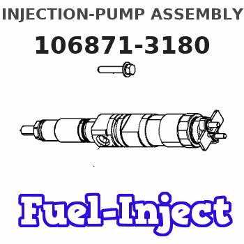
Information injection-pump assembly
ZEXEL
106871-3180
1068713180
HINO
220001296A
220001296a
Rating:
Service parts 106871-3180 INJECTION-PUMP ASSEMBLY:
1.
_
7.
COUPLING PLATE
8.
_
9.
_
11.
Nozzle and Holder
23600-1212
12.
Open Pre:MPa(Kqf/cm2)
21.6{220}
15.
NOZZLE SET
Include in #1:
106871-3180
as INJECTION-PUMP ASSEMBLY
Cross reference number
ZEXEL
106871-3180
1068713180
HINO
220001296A
220001296a
Zexel num
Bosch num
Firm num
Name
Calibration Data:
Adjustment conditions
Test oil
1404 Test oil ISO4113 or {SAEJ967d}
1404 Test oil ISO4113 or {SAEJ967d}
Test oil temperature
degC
40
40
45
Nozzle and nozzle holder
105780-8140
Bosch type code
EF8511/9A
Nozzle
105780-0000
Bosch type code
DN12SD12T
Nozzle holder
105780-2080
Bosch type code
EF8511/9
Opening pressure
MPa
17.2
Opening pressure
kgf/cm2
175
Injection pipe
Outer diameter - inner diameter - length (mm) mm 8-3-600
Outer diameter - inner diameter - length (mm) mm 8-3-600
Overflow valve
134424-0820
Overflow valve opening pressure
kPa
127
107
147
Overflow valve opening pressure
kgf/cm2
1.3
1.1
1.5
Tester oil delivery pressure
kPa
157
157
157
Tester oil delivery pressure
kgf/cm2
1.6
1.6
1.6
Direction of rotation (viewed from drive side)
Right R
Right R
Injection timing adjustment
Direction of rotation (viewed from drive side)
Right R
Right R
Injection order
1-8-6-2-
7-5-4-3
Pre-stroke
mm
4
3.9
4
Beginning of injection position
Drive side NO.1
Drive side NO.1
Difference between angles 1
Cal 1-8 deg. 45 44.5 45.5
Cal 1-8 deg. 45 44.5 45.5
Difference between angles 2
Cal 1-6 deg. 90 89.5 90.5
Cal 1-6 deg. 90 89.5 90.5
Difference between angles 3
Cyl.1-2 deg. 135 134.5 135.5
Cyl.1-2 deg. 135 134.5 135.5
Difference between angles 4
Cal 1-7 deg. 180 179.5 180.5
Cal 1-7 deg. 180 179.5 180.5
Difference between angles 5
Cal 1-5 deg. 225 224.5 225.5
Cal 1-5 deg. 225 224.5 225.5
Difference between angles 6
Cal 1-4 deg. 270 269.5 270.5
Cal 1-4 deg. 270 269.5 270.5
Difference between angles 7
Cal 1-3 deg. 315 314.5 315.5
Cal 1-3 deg. 315 314.5 315.5
Injection quantity adjustment
Adjusting point
A
Rack position
9.1
Pump speed
r/min
500
500
500
Average injection quantity
mm3/st.
107.2
104.2
110.2
Max. variation between cylinders
%
0
-4
4
Fixing the lever
*
Injection quantity adjustment_02
Adjusting point
B
Rack position
9.2
Pump speed
r/min
700
700
700
Average injection quantity
mm3/st.
111
109
113
Max. variation between cylinders
%
0
-2
2
Basic
*
Fixing the lever
*
Injection quantity adjustment_03
Adjusting point
C
Rack position
9.7
Pump speed
r/min
1200
1200
1200
Average injection quantity
mm3/st.
126.6
123.6
129.6
Max. variation between cylinders
%
0
-4
4
Fixing the lever
*
Injection quantity adjustment_04
Adjusting point
D
Rack position
6.4+-0.5
Pump speed
r/min
225
225
225
Average injection quantity
mm3/st.
13.7
10.7
16.7
Max. variation between cylinders
%
0
-15
15
Fixing the rack
*
Injection quantity adjustment_05
Adjusting point
E
Rack position
-
Pump speed
r/min
50
50
50
Average injection quantity
mm3/st.
122
112
132
Fixing the lever
*
Remarks
After startup boost setting
After startup boost setting
Timer adjustment
Pump speed
r/min
950+-50
Advance angle
deg.
0
0
0
Remarks
Start
Start
Timer adjustment_02
Pump speed
r/min
1100
Advance angle
deg.
1
0.5
1.5
Timer adjustment_03
Pump speed
r/min
1200
Advance angle
deg.
2
1.5
2.5
Remarks
Finish
Finish
Test data Ex:
Governor adjustment
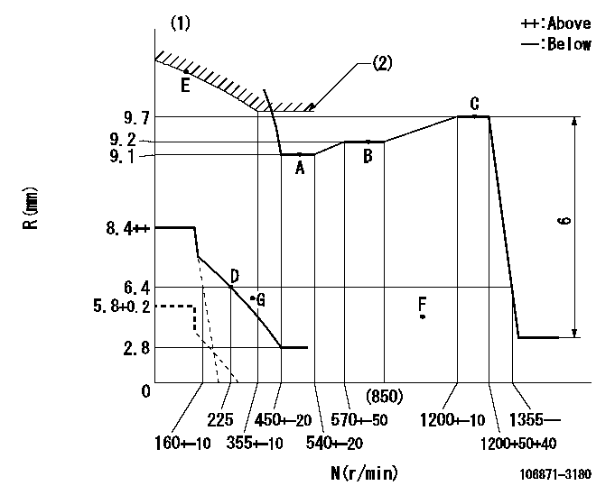
N:Pump speed
R:Rack position (mm)
(1)Beginning of damper spring operation: DL
(2)Excess fuel setting for starting: SXL
----------
DL=5.4-0.2mm SXL=9.7+0.2mm
----------
----------
DL=5.4-0.2mm SXL=9.7+0.2mm
----------
Speed control lever angle

F:Full speed
----------
----------
a=4deg+-5deg
----------
----------
a=4deg+-5deg
0000000901
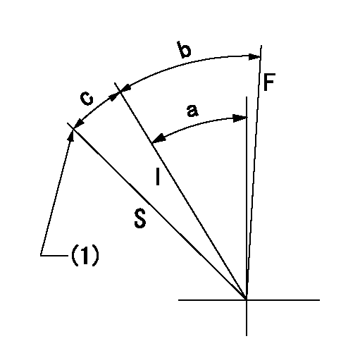
F:Full load
I:Idle
S:Stop
(1)Rack position aa (pump speed bb r/min )
----------
aa=5.8+0.2mm bb=0r/min
----------
a=32deg+-5deg b=33deg+-3deg c=19deg+4deg-5deg
----------
aa=5.8+0.2mm bb=0r/min
----------
a=32deg+-5deg b=33deg+-3deg c=19deg+4deg-5deg
0000001501 MICRO SWITCH
Switch adjustment
Adjust the bolt so that the lower lever position is obtained when the switch is turned ON.
(1)Speed N1
(2)Rack position Ra
----------
N1=325-25r/min Ra=6.4mm
----------
----------
N1=325-25r/min Ra=6.4mm
----------
Information:
Appendix
Configuration Information
Table 7
Over-Temp
Inlet Over-Temperature Alarm
Condition Expected Value
Enable Alarm Yes
Log Alarm Transitions Yes
Active Output During Alarm Output 1
Output function ON only during alarm
Assert Alarm Above
650 °C (1202 °F)
Hysteresis
20 °C (68 °F)
Upon Over Temperature extend alarm for 60 seconds
Table 8
Over-Pres
Over-Pressure Warning
Condition Expected Value
Enable Alarm Yes
Log Alarm Transitions Yes
Active Output During Alarm Output 1
Output Function ON only during alarm
Assert Alarm when the measured pressure exceeds 7" of Hg for 5% of the time during a 60 min measurement interval
Over-Pressure Alarm
Condition Expected Value
Enable Alarm Yes
Log Alarm Transitions Yes
Active Output During Alarm Output 2
Output Function Latched ON upon alarm
Assert alarm when the measured pressure exceeds 8" of Hg for 5% of the time during a 60 min measurement interval
Table 9
TC-Fail (1)
Open Thermocouple Detect
Condition Expected Value
Enable Alarm Yes
Log Alarm Transitions Yes
Output During Alarm Output 1
Output Function Latched ON upon alarm
Assert alarm if measured temperature is above
1000 °C (1832 °F)
Shorted Thermocouple Detect
Condition Expected Value
Enable Alarm Yes
Log Alarm Transitions Yes
Output During Alarm Output 1
Output Function Latched ON upon alarm
Assert alarm if pressure is greater than 1" of Hg for 10 min and measured temperature does not exceed
120 °C (248 °F)
( 1 ) Output selection applies to both open and shorted alarms
Table 10
Pressure Sensor Fail
No Change Alarm
Condition Expected Value
Enable Alarm Yes
Log Alarm Transitions Yes
Active Outputs During Alarm Output 1
Output Function Latched ON upon Alarm
Assert alarm if exhaust temperature is above
250 °C (482 °F) for 10 min and the pressure doesn't change by at least 0.25" of Hg
Negative Pressure Alarm
Condition Expected Value
Enable Alarm Yes
Log Alarm Transitions Yes
Active Output During Alarm Output 1
Output Function Latched ON during alarm
Assert Alarm if temperature is above
200 °C (392 °F) for 10 min and the pressure is less than −1" of