Information injection-pump assembly
ZEXEL
106871-2990
1068712990

Rating:
Cross reference number
ZEXEL
106871-2990
1068712990
Zexel num
Bosch num
Firm num
Name
Calibration Data:
Adjustment conditions
Test oil
1404 Test oil ISO4113 or {SAEJ967d}
1404 Test oil ISO4113 or {SAEJ967d}
Test oil temperature
degC
40
40
45
Nozzle and nozzle holder
105780-8140
Bosch type code
EF8511/9A
Nozzle
105780-0000
Bosch type code
DN12SD12T
Nozzle holder
105780-2080
Bosch type code
EF8511/9
Opening pressure
MPa
17.2
Opening pressure
kgf/cm2
175
Injection pipe
Outer diameter - inner diameter - length (mm) mm 8-3-600
Outer diameter - inner diameter - length (mm) mm 8-3-600
Overflow valve
131424-4620
Overflow valve opening pressure
kPa
255
221
289
Overflow valve opening pressure
kgf/cm2
2.6
2.25
2.95
Tester oil delivery pressure
kPa
157
157
157
Tester oil delivery pressure
kgf/cm2
1.6
1.6
1.6
Direction of rotation (viewed from drive side)
Right R
Right R
Injection timing adjustment
Direction of rotation (viewed from drive side)
Right R
Right R
Injection order
1-2-7-3-
4-5-6-8
Pre-stroke
mm
4.8
4.75
4.85
Beginning of injection position
Governor side NO.1
Governor side NO.1
Difference between angles 1
Cyl.1-2 deg. 45 44.5 45.5
Cyl.1-2 deg. 45 44.5 45.5
Difference between angles 2
Cal 1-7 deg. 90 89.5 90.5
Cal 1-7 deg. 90 89.5 90.5
Difference between angles 3
Cal 1-3 deg. 135 134.5 135.5
Cal 1-3 deg. 135 134.5 135.5
Difference between angles 4
Cal 1-4 deg. 180 179.5 180.5
Cal 1-4 deg. 180 179.5 180.5
Difference between angles 5
Cal 1-5 deg. 225 224.5 225.5
Cal 1-5 deg. 225 224.5 225.5
Difference between angles 6
Cal 1-6 deg. 270 269.5 270.5
Cal 1-6 deg. 270 269.5 270.5
Difference between angles 7
Cal 1-8 deg. 315 314.5 315.5
Cal 1-8 deg. 315 314.5 315.5
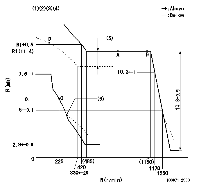
Injection quantity adjustment
Adjusting point
-
Rack position
11.4
Pump speed
r/min
700
700
700
Each cylinder's injection qty
mm3/st.
156
151
161
Basic
*
Fixing the rack
*
Standard for adjustment of the maximum variation between cylinders
*
Injection quantity adjustment_02
Adjusting point
C
Rack position
6.1+-0.5
Pump speed
r/min
225
225
225
Each cylinder's injection qty
mm3/st.
20
17
23
Fixing the rack
*
Standard for adjustment of the maximum variation between cylinders
*
Injection quantity adjustment_03
Adjusting point
A
Rack position
R1(11.4)
Pump speed
r/min
700
700
700
Average injection quantity
mm3/st.
156
155
157
Basic
*
Fixing the lever
*
Boost pressure
kPa
33.3
33.3
Boost pressure
mmHg
250
250
Injection quantity adjustment_04
Adjusting point
B
Rack position
R1(11.4)
Pump speed
r/min
1100
1100
1100
Average injection quantity
mm3/st.
164
157
171
Difference in delivery
mm3/st.
14
14
14
Fixing the lever
*
Boost pressure
kPa
33.3
33.3
Boost pressure
mmHg
250
250
Injection quantity adjustment_05
Adjusting point
D
Rack position
-
Pump speed
r/min
100
100
100
Average injection quantity
mm3/st.
130
90
170
Fixing the lever
*
Boost pressure
kPa
0
0
0
Boost pressure
mmHg
0
0
0
Boost compensator adjustment
Pump speed
r/min
650
650
650
Rack position
9.9
Boost pressure
kPa
8
8
8
Boost pressure
mmHg
60
60
60
Boost compensator adjustment_02
Pump speed
r/min
650
650
650
Rack position
10.8
Boost pressure
kPa
12
10.7
13.3
Boost pressure
mmHg
90
80
100
Boost compensator adjustment_03
Pump speed
r/min
650
650
650
Rack position
R1(11.4)
Boost pressure
kPa
20
13.3
26.7
Boost pressure
mmHg
150
100
200
Timer adjustment
Pump speed
r/min
(900+-50
)
Advance angle
deg.
0
0
0
Remarks
Start
Start
Timer adjustment_02
Pump speed
r/min
1100
Advance angle
deg.
4
3.5
4.5
Remarks
Finish
Finish
Test data Ex:
Governor adjustment
N:Pump speed
R:Rack position (mm)
(1)Lever ratio: RT
(2)Target shim dimension: TH
(3)Tolerance for racks not indicated: +-0.05mm.
(4)Boost compensator cancel stroke: BSL
(5)Boost compensator stroke: BCL
(6)Damper spring setting: DL
----------
RT=1 TH=2.5mm BSL=1.6mm BCL=1.5+-0.1mm DL=4.3-0.2mm
----------
----------
RT=1 TH=2.5mm BSL=1.6mm BCL=1.5+-0.1mm DL=4.3-0.2mm
----------
Speed control lever angle

F:Full speed
----------
----------
a=18deg+-5deg
----------
----------
a=18deg+-5deg
0000000901

F:Full load
I:Idle
(1)Stopper bolt setting
----------
----------
a=10deg+-5deg b=31.5deg+-3deg
----------
----------
a=10deg+-5deg b=31.5deg+-3deg
Stop lever angle
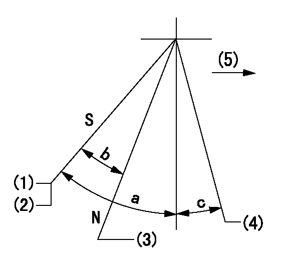
N:Engine manufacturer's normal use
S:Stop the pump.
(1)Rack position = aa
(2)Stopper bolt setting
(3)Rack position bb
(4)Free (at shipping)
(5)Drive side
----------
aa=4-0.5mm bb=14.6mm
----------
a=43deg+7deg-5deg b=30deg+-5deg c=(10.5deg)
----------
aa=4-0.5mm bb=14.6mm
----------
a=43deg+7deg-5deg b=30deg+-5deg c=(10.5deg)
0000001501 MICRO SWITCH
Adjustment of the micro-switch
Adjust the bolt to obtain the following lever position when the micro-switch is ON.
(1)Speed N1
(2)Rack position Ra
----------
N1=325r/min Ra=5.6+-0.1mm
----------
----------
N1=325r/min Ra=5.6+-0.1mm
----------
Timing setting

(1)Pump vertical direction
(2)Coupling's key groove position at No 1 cylinder's beginning of injection
(3)-
(4)-
----------
----------
a=(40deg)
----------
----------
a=(40deg)
Information:
Accidental engine starting can cause injury or death to personnel working on the equipment.To avoid accidental engine starting, disconnect the battery cable from the negative (−) battery terminal. Completely tape all metal surfaces of the disconnected battery cable end in order to prevent contact with other metal surfaces which could activate the engine electrical system.Place a Do Not Operate tag at the Start/Stop switch location to inform personnel that the equipment is being worked on.
2301A Electric Governor Control
The 2301A Electric Governor Control activates all of the components that are in the electric protection system. The components are activated in the same manner when the nonelectric governor is used. One difference exists in the main circuit. The fuel shutoff solenoid (FSOS) (line 43) is not used.When the electric governor control is used, the engine must run in a normal condition in order for the electric circuit to operate in the manner that is described below.
Current flows from the terminals (TS-28) (line 43) and (TS-31) (line 44), which are located on the terminal strip in the junction box.
Current from terminals (TS-28) (line 43) and (TS-31) (line 44) flows through the preregulator (PR) (line 48) or the fuse (F4) to the electric governor control.
When the engine flywheel is rotating, the current also flows through the electric governor actuator (EGA) (line 52). When a fault in the system causes the current to energize the slave relay (SR1), the following events occur in the electric circuit in order to stop the engine.
The slave relay (SR1) opens across the contacts (SR1-30) and (SR1-87a) (line 45). The relay closes across the contacts (SR1-30) and (SR1-87) (line 43).
When the circuit opens across contacts (SR1-30) and (SR1-87a), the current is stopped to the electric governor control.
Current to the electric governor actuator (EGA) is also stopped.
The mechanical spring load in the electric governor actuator (EGA) will now move the fuel control rod in order to stop fuel flow to the engine. Note: With the exception of the differences that are described in this section of the manual, all of the fault circuits in the electric protection system are identical for the 2301A Electric Governor Control and for the nonelectric governor control.
Illustration 5 g00292615
Junction Box Wiring for ETR protection system with OP, WT, and OS that does not require