Information injection-pump assembly
ZEXEL
106871-2530
1068712530
MITSUBISHI
ME066560
me066560

Rating:
Cross reference number
ZEXEL
106871-2530
1068712530
MITSUBISHI
ME066560
me066560
Zexel num
Bosch num
Firm num
Name
Calibration Data:
Adjustment conditions
Test oil
1404 Test oil ISO4113 or {SAEJ967d}
1404 Test oil ISO4113 or {SAEJ967d}
Test oil temperature
degC
40
40
45
Nozzle and nozzle holder
105780-8140
Bosch type code
EF8511/9A
Nozzle
105780-0000
Bosch type code
DN12SD12T
Nozzle holder
105780-2080
Bosch type code
EF8511/9
Opening pressure
MPa
17.2
Opening pressure
kgf/cm2
175
Injection pipe
Outer diameter - inner diameter - length (mm) mm 8-3-600
Outer diameter - inner diameter - length (mm) mm 8-3-600
Overflow valve opening pressure
kPa
157
123
191
Overflow valve opening pressure
kgf/cm2
1.6
1.25
1.95
Tester oil delivery pressure
kPa
157
157
157
Tester oil delivery pressure
kgf/cm2
1.6
1.6
1.6
Direction of rotation (viewed from drive side)
Right R
Right R
Injection timing adjustment
Direction of rotation (viewed from drive side)
Right R
Right R
Injection order
1-2-7-3-
4-5-6-8
Pre-stroke
mm
4.8
4.75
4.85
Beginning of injection position
Governor side NO.1
Governor side NO.1
Difference between angles 1
Cyl.1-2 deg. 45 44.5 45.5
Cyl.1-2 deg. 45 44.5 45.5
Difference between angles 2
Cal 1-7 deg. 90 89.5 90.5
Cal 1-7 deg. 90 89.5 90.5
Difference between angles 3
Cal 1-3 deg. 135 134.5 135.5
Cal 1-3 deg. 135 134.5 135.5
Difference between angles 4
Cal 1-4 deg. 180 179.5 180.5
Cal 1-4 deg. 180 179.5 180.5
Difference between angles 5
Cal 1-5 deg. 225 224.5 225.5
Cal 1-5 deg. 225 224.5 225.5
Difference between angles 6
Cal 1-6 deg. 270 269.5 270.5
Cal 1-6 deg. 270 269.5 270.5
Difference between angles 7
Cal 1-8 deg. 315 314.5 315.5
Cal 1-8 deg. 315 314.5 315.5
Injection quantity adjustment
Adjusting point
-
Rack position
10.4
Pump speed
r/min
700
700
700
Each cylinder's injection qty
mm3/st.
118
114.5
121.5
Basic
*
Fixing the rack
*
Standard for adjustment of the maximum variation between cylinders
*
Injection quantity adjustment_02
Adjusting point
C
Rack position
6.8+-0.5
Pump speed
r/min
225
225
225
Each cylinder's injection qty
mm3/st.
20
17
23
Fixing the rack
*
Standard for adjustment of the maximum variation between cylinders
*
Injection quantity adjustment_03
Adjusting point
A
Rack position
R1(10.4)
Pump speed
r/min
700
700
700
Average injection quantity
mm3/st.
118
117
119
Fixing the lever
*
Injection quantity adjustment_04
Adjusting point
B
Rack position
R1(10.4)
Pump speed
r/min
1100
1100
1100
Average injection quantity
mm3/st.
124
118.8
129.2
Difference in delivery
mm3/st.
10.4
10.4
10.4
Fixing the lever
*
Injection quantity adjustment_05
Adjusting point
E
Rack position
-
Pump speed
r/min
100
100
100
Average injection quantity
mm3/st.
150
130
170
Fixing the lever
*
Remarks
After startup boost setting
After startup boost setting
Timer adjustment
Pump speed
r/min
950--
Advance angle
deg.
0
0
0
Remarks
Start
Start
Timer adjustment_02
Pump speed
r/min
900
Advance angle
deg.
0.5
Timer adjustment_03
Pump speed
r/min
1100
Advance angle
deg.
5
4.5
5.5
Timer adjustment_04
Pump speed
r/min
(1150)
Advance angle
deg.
6.5
6
7
Remarks
Finish
Finish
Test data Ex:
Governor adjustment
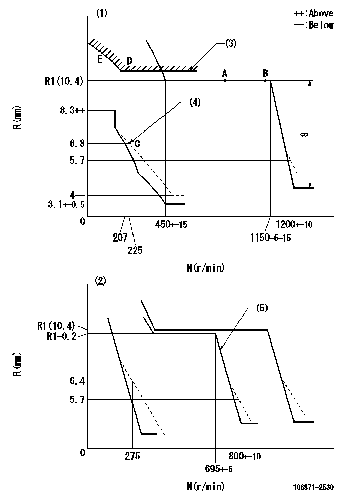
N:Pump speed
R:Rack position (mm)
(1)Adjust with speed control lever at full position (minimum-maximum speed specification)
(2)Adjust with the load control lever in the full position (variable speed specification).
(3)Excess fuel setting for starting: SXL
(4)Damper spring setting
(5)When air cylinder is operating.
----------
SXL=13+-0.1mm
----------
----------
SXL=13+-0.1mm
----------
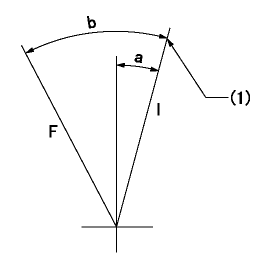
Speed control lever angle

F:Full speed
I:Idle
(1)Pump speed = aa
(2)Pump speed = bb
(3)Pump speed cc
(4)Air cylinder's adjustable range
----------
aa=1150r/min bb=275r/min cc=695r/min
----------
a=13deg b=8deg+-5deg c=13deg+-5deg d=24deg+-5deg
----------
aa=1150r/min bb=275r/min cc=695r/min
----------
a=13deg b=8deg+-5deg c=13deg+-5deg d=24deg+-5deg
0000000901
F:Full load
I:Idle
(1)Stopper bolt setting
----------
----------
a=10deg+-5deg b=26.5deg+-3deg
----------
----------
a=10deg+-5deg b=26.5deg+-3deg
Stop lever angle
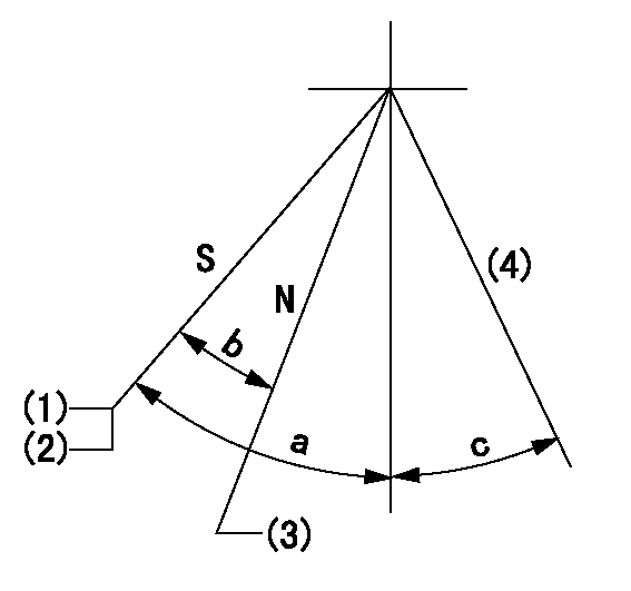
N:Pump normal
S:Stop the pump.
(1)Rack position = aa
(2)Stopper bolt setting
(3)Rack position bb
(4)Free (at shipping)
----------
aa=4.7-0.5mm bb=12.4mm
----------
a=43deg+7deg-5deg b=21.5deg+-5deg c=(10.5deg)
----------
aa=4.7-0.5mm bb=12.4mm
----------
a=43deg+7deg-5deg b=21.5deg+-5deg c=(10.5deg)
0000001501 MICRO SWITCH
Adjustment of the micro-switch
Adjust the bolt to obtain the following lever position when the micro-switch is ON.
(1)Speed N1
(2)Rack position Ra
----------
N1=325+-5r/min Ra=6.3mm
----------
----------
N1=325+-5r/min Ra=6.3mm
----------
Information:
When using Cat ELC, do not use conventional SCAs, or, if equipped, SCA maintenance elements. In order to avoid SCA contamination of an ELC system, remove the SCA element base and plug off or bypass the coolant lines.
Cat ELC Cooling System Cleaning
Note: If the cooling system is already using Cat ELC, cleaning agents are not required at the specified coolant change interval. Cleaning agents are only required if the system has been contaminated by the addition of some other type of coolant or by cooling system damage.Clean water is the only cleaning agent that is required when Cat ELC is drained from a properly maintained cooling system.After the cooling system is drained and after the cooling system is refilled, operate the engine while the cooling system filler cap is removed. Operate the engine until the coolant level reaches the normal operating temperature and until the coolant level stabilizes. As needed, add the coolant mixture in order to fill the system to the proper level.Recycling Cat ELC
Cat ELC can be recycled into conventional coolants. The drained coolant mixture can be distilled in order to remove the ethylene glycol and the water. The ethylene glycol and the water can be reused. The distilled material does not contain the additives that are classified as either Cat ELC or Cat DEAC. Consult your Cat dealer for more information. Recycled coolants should meet the most current revision level of "ASTM D6210".Changing to Cat ELC
To change from heavy-duty coolant/antifreeze to the Cat ELC, perform the following steps:
Care must be taken to ensure that fluids are contained during performance of inspection, maintenance, testing, adjusting and repair of the product. Be prepared to collect the fluid with suitable containers before opening any compartment or disassembling any component containing fluids.Refer to Special Publication, NENG2500, "Caterpillar Dealer Service Tool Catalog" and to Special Publication, PECJ0003, "Cat Shop Supplies and Tools" for tools and supplies suitable to collect and contain fluids on Cat products.Dispose of all fluids according to applicable regulations and mandates.
Drain the coolant into a suitable container.
Dispose of the coolant according to local regulations.
If equipped, remove the empty SCA maintenance element and remove the element base. Plug the coolant lines or bypass the coolant lines.
Do not leave an empty SCA maintenance element on a system that is filled with Cat ELC.The element housing may corrode and leak causing an engine failure.Remove the SCA element base and plug off or by-pass the coolant lines.
Flush the system with clean water in order to remove any debris.
Use Cat Quick Flush Cooling System Cleaner for cooling systems in order to clean the system. Cat Quick Flush Cooling System Cleaner is available in various sizes. Part numbers are 4C-4609 ( 0.5 L (0.125 US gal)) through 4C-4613 ( 208.2 L (55 US gal)). Follow the instructions on the label using a 6-10% concentration of cleaner in water.
Drain the cleaner into a suitable container. Flush the cooling system with clean water. Note: Deposits that remain in the system may be loosened and removed