Information injection-pump assembly
ZEXEL
106871-2510
1068712510
MITSUBISHI
ME066540
me066540

Rating:
Cross reference number
ZEXEL
106871-2510
1068712510
MITSUBISHI
ME066540
me066540
Zexel num
Bosch num
Firm num
Name
Calibration Data:
Adjustment conditions
Test oil
1404 Test oil ISO4113 or {SAEJ967d}
1404 Test oil ISO4113 or {SAEJ967d}
Test oil temperature
degC
40
40
45
Nozzle and nozzle holder
105780-8140
Bosch type code
EF8511/9A
Nozzle
105780-0000
Bosch type code
DN12SD12T
Nozzle holder
105780-2080
Bosch type code
EF8511/9
Opening pressure
MPa
17.2
Opening pressure
kgf/cm2
175
Injection pipe
Outer diameter - inner diameter - length (mm) mm 8-3-600
Outer diameter - inner diameter - length (mm) mm 8-3-600
Overflow valve opening pressure
kPa
157
123
191
Overflow valve opening pressure
kgf/cm2
1.6
1.25
1.95
Tester oil delivery pressure
kPa
157
157
157
Tester oil delivery pressure
kgf/cm2
1.6
1.6
1.6
Direction of rotation (viewed from drive side)
Right R
Right R
Injection timing adjustment
Direction of rotation (viewed from drive side)
Right R
Right R
Injection order
1-2-7-3-
4-5-6-8
Pre-stroke
mm
4.8
4.75
4.85
Beginning of injection position
Governor side NO.1
Governor side NO.1
Difference between angles 1
Cyl.1-2 deg. 45 44.5 45.5
Cyl.1-2 deg. 45 44.5 45.5
Difference between angles 2
Cal 1-7 deg. 90 89.5 90.5
Cal 1-7 deg. 90 89.5 90.5
Difference between angles 3
Cal 1-3 deg. 135 134.5 135.5
Cal 1-3 deg. 135 134.5 135.5
Difference between angles 4
Cal 1-4 deg. 180 179.5 180.5
Cal 1-4 deg. 180 179.5 180.5
Difference between angles 5
Cal 1-5 deg. 225 224.5 225.5
Cal 1-5 deg. 225 224.5 225.5
Difference between angles 6
Cal 1-6 deg. 270 269.5 270.5
Cal 1-6 deg. 270 269.5 270.5
Difference between angles 7
Cal 1-8 deg. 315 314.5 315.5
Cal 1-8 deg. 315 314.5 315.5
Injection quantity adjustment
Adjusting point
-
Rack position
10.4
Pump speed
r/min
700
700
700
Each cylinder's injection qty
mm3/st.
118
114.5
121.5
Basic
*
Fixing the rack
*
Standard for adjustment of the maximum variation between cylinders
*
Injection quantity adjustment_02
Adjusting point
C
Rack position
6.8+-0.5
Pump speed
r/min
225
225
225
Each cylinder's injection qty
mm3/st.
20
17
23
Fixing the rack
*
Standard for adjustment of the maximum variation between cylinders
*
Injection quantity adjustment_03
Adjusting point
A
Rack position
R1(10.4)
Pump speed
r/min
700
700
700
Average injection quantity
mm3/st.
118
117
119
Basic
*
Fixing the lever
*
Injection quantity adjustment_04
Adjusting point
B
Rack position
R1(10.4)
Pump speed
r/min
1100
1100
1100
Average injection quantity
mm3/st.
124
118.8
129.2
Difference in delivery
mm3/st.
10.4
10.4
10.4
Fixing the lever
*
Injection quantity adjustment_05
Adjusting point
E
Rack position
-
Pump speed
r/min
100
100
100
Average injection quantity
mm3/st.
160
140
180
Fixing the lever
*
Remarks
After startup boost setting
After startup boost setting
Timer adjustment
Pump speed
r/min
950--
Advance angle
deg.
0
0
0
Remarks
Start
Start
Timer adjustment_02
Pump speed
r/min
900
Advance angle
deg.
0.5
Timer adjustment_03
Pump speed
r/min
1100
Advance angle
deg.
5
4.5
5.5
Timer adjustment_04
Pump speed
r/min
(1150)
Advance angle
deg.
6.5
6
7
Remarks
Finish
Finish
Test data Ex:
Governor adjustment
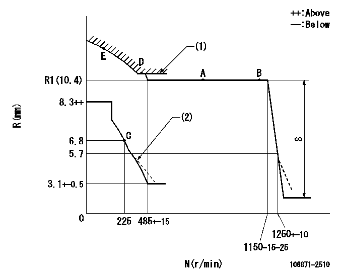
N:Pump speed
R:Rack position (mm)
(1)Excess fuel setting for starting: SXL
(2)Beginning of damper spring operation: DL
----------
SXL=11.1+-0.1mm DL=5-0.2mm
----------
----------
SXL=11.1+-0.1mm DL=5-0.2mm
----------
Speed control lever angle

F:Full speed
----------
----------
a=21deg+-5deg
----------
----------
a=21deg+-5deg
0000000901
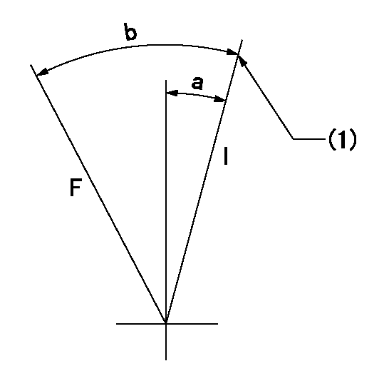
F:Full load
I:Idle
(1)Stopper bolt setting
----------
----------
a=10deg+-5deg b=26.5deg+-3deg
----------
----------
a=10deg+-5deg b=26.5deg+-3deg
Stop lever angle
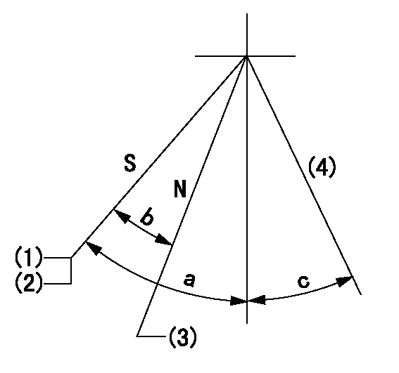
N:Pump normal
S:Stop the pump.
(1)Rack position = aa
(2)Stopper bolt setting
(3)Rack position bb
(4)Free (at shipping)
----------
aa=4.7-0.5mm bb=12.4mm
----------
a=43deg+7deg-5deg b=21.5deg+-5deg c=(10.5deg)
----------
aa=4.7-0.5mm bb=12.4mm
----------
a=43deg+7deg-5deg b=21.5deg+-5deg c=(10.5deg)
0000001501 MICRO SWITCH
Adjustment of the micro-switch
Adjust the bolt to obtain the following lever position when the micro-switch is ON.
(1)Speed N1
(2)Rack position Ra
----------
N1=325+-5r/min Ra=6.3mm
----------
----------
N1=325+-5r/min Ra=6.3mm
----------
Timing setting

(1)Pump vertical direction
(2)Coupling's key groove position at No 1 cylinder's beginning of injection
(3)-
(4)-
----------
----------
a=(40deg)
----------
----------
a=(40deg)
Information:
PARTS NEEDED
Qty
Part Number Description
6 3879434 INJECTOR GP-FUEL
1 5638152 FILTER-LUBE
In order to allow equitable parts availability to all participating dealers, please limit your initial parts order to not exceed 1% of dealership population. This is an initial order recommendation only, and the ultimate responsibility for ordering the total number of parts needed to satisfy the program lies with the dealer.
ACTION REQUIRED
Upon failure of an injector or multiple injectors, replace the entire set of fuel injectors with six 3879434 fuel injectors and install a new 5638152 fuel filter.
Refer to Disassembly and Assembly, RENR9579, Unit Injector - Remove, and Unit Injector - Install.
SERVICE CLAIM ALLOWANCES
Product smu/age whichever comes first Caterpillar Dealer Suggested Customer Suggested
Parts % Labor Hrs% Parts % Labor Hrs% Parts % Labor Hrs%
0-4000 hrs,
0-24 mo 100.0% 100.0% 0.0% 0.0% 0.0% 0.0%
4001-8000 hrs,
25-36 mo 33.0% 50.0% 0.0% 0.0% 50.0% 50.0%
This is a 12.9-hour job
PARTS DISPOSITION
Handle the parts in accordance with your Warranty Bulletin on warranty parts handling.