Information injection-pump assembly
ZEXEL
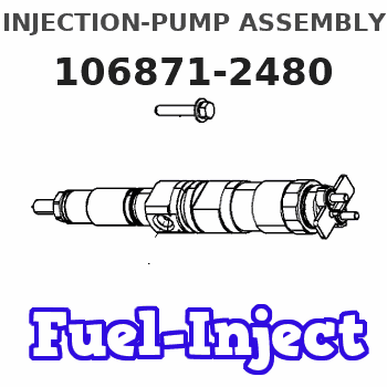
106871-2480
1068712480
MITSUBISHI
ME066507
me066507
Rating:
Cross reference number
ZEXEL
106871-2480
1068712480
MITSUBISHI
ME066507
me066507
Zexel num
Bosch num
Firm num
Name
106871-2480
ME066507 MITSUBISHI
INJECTION-PUMP ASSEMBLY
8DC9 * K
8DC9 * K
Calibration Data:
Adjustment conditions
Test oil
1404 Test oil ISO4113 or {SAEJ967d}
1404 Test oil ISO4113 or {SAEJ967d}
Test oil temperature
degC
40
40
45
Nozzle and nozzle holder
105780-8140
Bosch type code
EF8511/9A
Nozzle
105780-0000
Bosch type code
DN12SD12T
Nozzle holder
105780-2080
Bosch type code
EF8511/9
Opening pressure
MPa
17.2
Opening pressure
kgf/cm2
175
Injection pipe
Outer diameter - inner diameter - length (mm) mm 8-3-600
Outer diameter - inner diameter - length (mm) mm 8-3-600
Overflow valve
132424-0620
Overflow valve opening pressure
kPa
157
123
191
Overflow valve opening pressure
kgf/cm2
1.6
1.25
1.95
Tester oil delivery pressure
kPa
157
157
157
Tester oil delivery pressure
kgf/cm2
1.6
1.6
1.6
Direction of rotation (viewed from drive side)
Right R
Right R
Injection timing adjustment
Direction of rotation (viewed from drive side)
Right R
Right R
Injection order
1-2-7-3-
4-5-6-8
Pre-stroke
mm
4.8
4.75
4.85
Beginning of injection position
Governor side NO.1
Governor side NO.1
Difference between angles 1
Cyl.1-2 deg. 45 44.5 45.5
Cyl.1-2 deg. 45 44.5 45.5
Difference between angles 2
Cal 1-7 deg. 90 89.5 90.5
Cal 1-7 deg. 90 89.5 90.5
Difference between angles 3
Cal 1-3 deg. 135 134.5 135.5
Cal 1-3 deg. 135 134.5 135.5
Difference between angles 4
Cal 1-4 deg. 180 179.5 180.5
Cal 1-4 deg. 180 179.5 180.5
Difference between angles 5
Cal 1-5 deg. 225 224.5 225.5
Cal 1-5 deg. 225 224.5 225.5
Difference between angles 6
Cal 1-6 deg. 270 269.5 270.5
Cal 1-6 deg. 270 269.5 270.5
Difference between angles 7
Cal 1-8 deg. 315 314.5 315.5
Cal 1-8 deg. 315 314.5 315.5
Injection quantity adjustment
Adjusting point
-
Rack position
9.2
Pump speed
r/min
700
700
700
Each cylinder's injection qty
mm3/st.
93
90.2
95.8
Basic
*
Fixing the rack
*
Standard for adjustment of the maximum variation between cylinders
*
Injection quantity adjustment_02
Adjusting point
C
Rack position
6.8+-0.5
Pump speed
r/min
200
200
200
Each cylinder's injection qty
mm3/st.
20
17
23
Fixing the rack
*
Standard for adjustment of the maximum variation between cylinders
*
Injection quantity adjustment_03
Adjusting point
A
Rack position
R1(9.2)
Pump speed
r/min
700
700
700
Average injection quantity
mm3/st.
93
92
94
Fixing the lever
*
Injection quantity adjustment_04
Adjusting point
B
Rack position
R1(9.2)
Pump speed
r/min
1100
1100
1100
Average injection quantity
mm3/st.
104
99.8
108.2
Difference in delivery
mm3/st.
8.4
8.4
8.4
Fixing the lever
*
Timer adjustment
Pump speed
r/min
600+-50
Advance angle
deg.
0
0
0
Remarks
Start
Start
Timer adjustment_02
Pump speed
r/min
700
Advance angle
deg.
0.7
0.2
1.2
Timer adjustment_03
Pump speed
r/min
850
Advance angle
deg.
2
1.5
2.5
Timer adjustment_04
Pump speed
r/min
1000
Advance angle
deg.
3.6
3.1
4.1
Timer adjustment_05
Pump speed
r/min
1150
Advance angle
deg.
5.5
5
6
Remarks
Finish
Finish
Test data Ex:
Governor adjustment
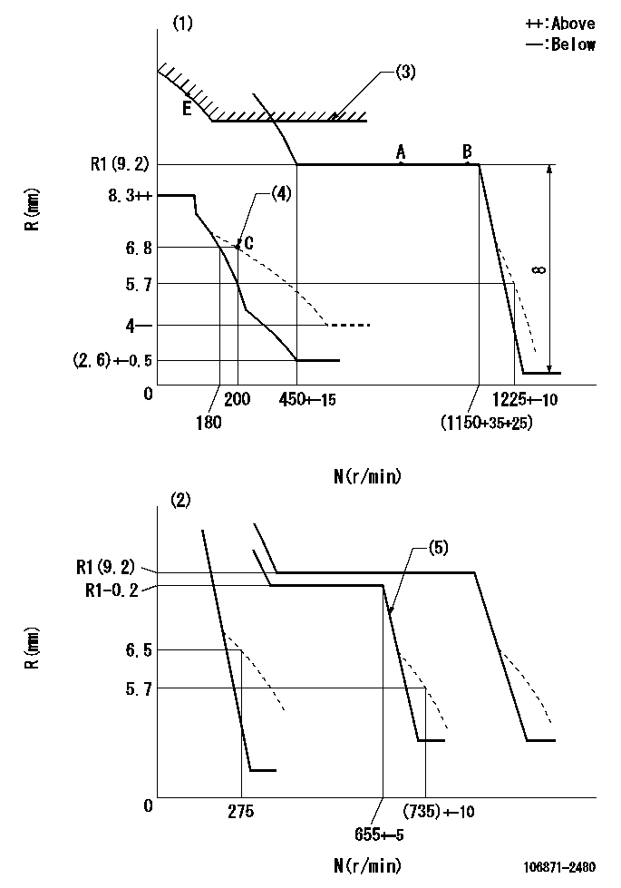
N:Pump speed
R:Rack position (mm)
(1)Adjust with speed control lever at full position (minimum-maximum speed specification)
(2)Adjust with the load control lever in the full position (variable speed specification).
(3)Excess fuel setting for starting: SXL
(4)Damper spring setting
(5)When air cylinder is operating.
----------
SXL=R1(9.2)+3+2.8mm
----------
----------
SXL=R1(9.2)+3+2.8mm
----------
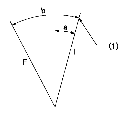
Speed control lever angle

F:Full speed
I:Idle
(1)Pump speed = aa
(2)Pump speed = bb
(3)Pump speed cc
(4)Possible adjusting range
----------
aa=(1150)r/min bb=655r/min cc=275r/min
----------
a=14deg b=9deg+-5deg c=16deg+-5deg d=(20deg)+-5deg
----------
aa=(1150)r/min bb=655r/min cc=275r/min
----------
a=14deg b=9deg+-5deg c=16deg+-5deg d=(20deg)+-5deg
0000000901
F:Full load
I:Idle
(1)Stopper bolt setting
----------
----------
a=10deg+-5deg b=(24deg)+-3deg
----------
----------
a=10deg+-5deg b=(24deg)+-3deg
Stop lever angle
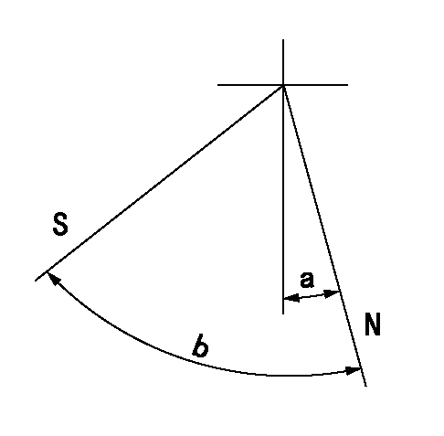
N:Pump normal
S:Stop the pump.
----------
----------
a=10deg+-5deg b=64deg+-5deg
----------
----------
a=10deg+-5deg b=64deg+-5deg
0000001501 MICRO SWITCH
Adjustment of the micro-switch
Adjust the bolt to obtain the following lever position when the micro-switch is ON.
(1)Speed N1
(2)Rack position Ra
----------
N1=325+-5r/min Ra=6.3mm
----------
----------
N1=325+-5r/min Ra=6.3mm
----------
0000001601 2-STAGE CHANGEOVER DEVICE

RFD governor 2 stage changeover mechanism adjustment outline
(A) Bolt
(B) bolt
(c) Nut
(D) Return spring
(E) Bolt
(F) Bolt
(G) Screw
(H) Bolt
(I) Load lever
(J) Speed lever
(K) Air cylinder
(M Air inlet
Figure 1 is only for reference. Lever shape, etc, may vary.
1. Minimum-maximum speed specification adjustment (when running)
(a) Without applying air to the air cylinder, loosen bolts (A) and (B).
(1)High speed return L setting
(a) In the speed range Nf~Nf - 300r/min, adjust using the speed adjusting bolt to determine the temporary beginning of high speed control speed.
(b) Determine the rack position in the vicinity of Rf using the full load lever.
(c) Increase speed and confirm return distance L.
(d) Adjust using the tension lever bolt to obtain L.
(2)Setting full load rack position Rf
(a) Move the load control lever to the full side.
(b) Adjust the full load adjusting bolt so that Rf can be obtained, then fix.
(3)Setting the beginning of high speed operation Nf
(a) Adjust using bolt (E) so that Nf can be obtained, and then fix.
(4)Idle control setting (Re, Ni, Rc)
(a) Set the speed at Ns + 200r/min and move the load control lever to the idle side.
(b) Fix the lever in the position where Re can be obtained.
(c) Next, decrease speed to Ni and screw in the idle spring.
(d) Adjust to obtain rack position Ri.
(e) Increase the speed and after confirming that the rack position is Re at Ns, set the speed at 0.
(f) Confirm protrusion position Rc at idle.
(5)Damper spring adjustment
(a) Increase speed and set the speed at the rack position Rd - 0.1 mm
(b) Set using the damper spring so that the rack position Rd can be obtained.
(c) When Rd is not specified, Rd = Ri - 0.5 mm.
(6)High speed droop confirmation
(a) Return the load control lever to the full load lever position.
(b) Increase the speed and confirm that Rf can be obtained at Nf r/min.
(c) Confirm that speed is Nh at rack position Rh.
2. Variable speed specification adjustment (at operation)
(a) Remove return spring (D).
(b) Apply air pressure of 245~294 kPa {2.5~3 kg/cm2} to the air cylinder.
(c) Perform the following adjustment in this condition.
(1)Setting full load rack position Rf'
(a) Pull the load lever to the idle side.
(b) Obtain rack position Rf' using the nut (C). (Pump speed is Nf'-50 r/min.)
(2)Setting full speed Nf'
(a) Adjust using bolt (B) so that Nf can be obtained, and then fix.
(3)Low speed side setting
(a) At 350r/min, set bolt (F) at beginning of governor operation position, then fix.
3. Bolt (A) adjustment
(1)Install return spring (D) and perform the adjustments below at air pressure 0.
(a) Set at speed Nf using bolt (E).
(b) Screw in bolt (A).
(c) Screw in 1 more turn from the speed lever contact position
(d) Fix bolt (A).
(e) At this time confirm that the air cylinder's shaft moves approximately 1 mm towards the governor.
4. Lever operation confirmation using the air cylinder
(1)Apply 588 kPa {6 kg/cm2} air pressure to the air cylinder.
(2)Confirm that the cylinder piston is moved 50 mm by the spring (D).
----------
----------
----------
----------
Information:
26Feb2020
U-93
A-70
D-86
O-82
Parts stock action only
PRODUCT IMPROVEMENT PROGRAM FOR INSPECTING AND POSSIBLY REMOVING CERTAIN 471-6029 DEF INJECTOR AND MOUNTING GROUPS FROM DEALER PARTS STOCK
108I 7750 PI70799
Caterpillar’s obligations under this Service Letter are subject to, and shall not apply in contravention of, the laws, rules, regulations, directives, ordinances, orders, or statutes of the United States, or of any other applicable jurisdiction, without recourse or liability with respect to Caterpillar.
When submitting claim for Parts Stock Action, Use the appropriate 99Z as the s/n, the appropriate Service Letter Program Number as the Part number in the Part Causing Failure field, "7751" as the Group Number, "56" as the Description Code.
The information supplied in this service letter may not be valid after the termination date of this program.Do not perform the work outlined in this Service Letter after the termination date without first contacting your Caterpillar product analyst.
TERMINATION DATE
31May2020
PROBLEM
A defined batch of existing 471-6029 DEF Injector and Mounting Groups can fail under certain conditions.
ACTION REQUIRED
Inspect all 471-6029 DEF Injector and Mounting Groups in dealer parts stock.
Open the packaging and visually inspect the DEF injector.
If the DEF injector's upper body molding mark is an A or B, then the DEF injector is acceptable to use. Repackage the DEF injector and mark the packaging as inspected per this program and place the part back into dealer parts stock.
If the DEF injector's upper body molding mark is a 1 or 2, then remove the part from dealer parts stock. Refer to the Parts Disposition.
Image 1 shows the molding marks and location.
Image1
SERVICE CLAIM ALLOWANCES
Submit one claim for all parts removed from dealer parts stock.
PARTS DISPOSITION
NACD:
Hold all 471-6029 DEF Injector and Mounting Groups removed from dealer parts stock for a Parts Return Request (PRR). A Parts Return Request (PRR) will be issued to you through the Send-It-Back process after the claim is submitted. Make sure to list the service letter program number on the packing slip and include the closed work order paperwork. Handle all other parts in accordance with your Warranty Bulletin on warranty parts handling.
If a Parts Return Request (PRR) is not issued to you after 30 days through the Send-It-Back process, handle the parts in accordance with your warranty bulletin on warranty parts handling.
EAME, LACD, and APD:
Hold all 471-6029 DEF Injector and Mounting Groups removed from dealer parts stock for 30 days for a possible Parts Return Request (PRR). Make sure to list the service letter program number on the packing slip and include the closed work order paperwork. Handle all other parts in accordance with your Warranty Bulletin on warranty parts handling.
If a Parts Return Request (PRR) is not issued to you after 30 days through the Send-It-Back process, handle the parts in accordance with your warranty bulletin on warranty parts handling.
Have questions with 106871-2480?
Group cross 106871-2480 ZEXEL
Mitsubishi
106871-2480
ME066507
INJECTION-PUMP ASSEMBLY
8DC9
8DC9