Information injection-pump assembly
BOSCH
9 400 618 090
9400618090
ZEXEL
106871-2450
1068712450
MITSUBISHI
ME066505
me066505
Rating:
Cross reference number
BOSCH
9 400 618 090
9400618090
ZEXEL
106871-2450
1068712450
MITSUBISHI
ME066505
me066505
Zexel num
Bosch num
Firm num
Name
106871-2450
9 400 618 090
ME066505 MITSUBISHI
INJECTION-PUMP ASSEMBLY
8DC8 * K
8DC8 * K
Calibration Data:
Adjustment conditions
Test oil
1404 Test oil ISO4113 or {SAEJ967d}
1404 Test oil ISO4113 or {SAEJ967d}
Test oil temperature
degC
40
40
45
Nozzle and nozzle holder
105780-8140
Bosch type code
EF8511/9A
Nozzle
105780-0000
Bosch type code
DN12SD12T
Nozzle holder
105780-2080
Bosch type code
EF8511/9
Opening pressure
MPa
17.2
Opening pressure
kgf/cm2
175
Injection pipe
Outer diameter - inner diameter - length (mm) mm 8-3-600
Outer diameter - inner diameter - length (mm) mm 8-3-600
Overflow valve
131424-0620
Overflow valve opening pressure
kPa
157
123
191
Overflow valve opening pressure
kgf/cm2
1.6
1.25
1.95
Tester oil delivery pressure
kPa
157
157
157
Tester oil delivery pressure
kgf/cm2
1.6
1.6
1.6
Direction of rotation (viewed from drive side)
Right R
Right R
Injection timing adjustment
Direction of rotation (viewed from drive side)
Right R
Right R
Injection order
1-2-7-3-
4-5-6-8
Pre-stroke
mm
4.8
4.75
4.85
Beginning of injection position
Governor side NO.1
Governor side NO.1
Difference between angles 1
Cyl.1-2 deg. 45 44.5 45.5
Cyl.1-2 deg. 45 44.5 45.5
Difference between angles 2
Cal 1-7 deg. 90 89.5 90.5
Cal 1-7 deg. 90 89.5 90.5
Difference between angles 3
Cal 1-3 deg. 135 134.5 135.5
Cal 1-3 deg. 135 134.5 135.5
Difference between angles 4
Cal 1-4 deg. 180 179.5 180.5
Cal 1-4 deg. 180 179.5 180.5
Difference between angles 5
Cal 1-5 deg. 225 224.5 225.5
Cal 1-5 deg. 225 224.5 225.5
Difference between angles 6
Cal 1-6 deg. 270 269.5 270.5
Cal 1-6 deg. 270 269.5 270.5
Difference between angles 7
Cal 1-8 deg. 315 314.5 315.5
Cal 1-8 deg. 315 314.5 315.5
Injection quantity adjustment
Adjusting point
-
Rack position
9
Pump speed
r/min
700
700
700
Each cylinder's injection qty
mm3/st.
85
82.4
87.6
Basic
*
Fixing the rack
*
Standard for adjustment of the maximum variation between cylinders
*
Injection quantity adjustment_02
Adjusting point
C
Rack position
6.8+-0.5
Pump speed
r/min
200
200
200
Each cylinder's injection qty
mm3/st.
20
17
23
Fixing the rack
*
Standard for adjustment of the maximum variation between cylinders
*
Injection quantity adjustment_03
Adjusting point
A
Rack position
R1(9)
Pump speed
r/min
700
700
700
Average injection quantity
mm3/st.
85
84
86
Fixing the lever
*
Injection quantity adjustment_04
Adjusting point
B
Rack position
R1(9)
Pump speed
r/min
1100
1100
1100
Average injection quantity
mm3/st.
96
93.1
98.9
Difference in delivery
mm3/st.
7.8
7.8
7.8
Fixing the lever
*
Injection quantity adjustment_05
Adjusting point
E
Rack position
-
Pump speed
r/min
100
100
100
Average injection quantity
mm3/st.
130
90
170
Fixing the lever
*
Remarks
After startup boost setting
After startup boost setting
Injection quantity adjustment_06
Adjusting point
G
Rack position
R2(8.6)
Pump speed
r/min
700
700
700
Average injection quantity
mm3/st.
80
79
81
Fixing the lever
*
Remarks
At air cylinder operation
At air cylinder operation
Timer adjustment
Pump speed
r/min
600+-50
Advance angle
deg.
0
0
0
Remarks
Start
Start
Timer adjustment_02
Pump speed
r/min
700
Advance angle
deg.
0.7
0.2
1.2
Timer adjustment_03
Pump speed
r/min
850
Advance angle
deg.
2
1.5
2.5
Timer adjustment_04
Pump speed
r/min
1000
Advance angle
deg.
3.6
3.1
4.1
Timer adjustment_05
Pump speed
r/min
1150
Advance angle
deg.
5.5
5
6
Remarks
Finish
Finish
Test data Ex:
Governor adjustment
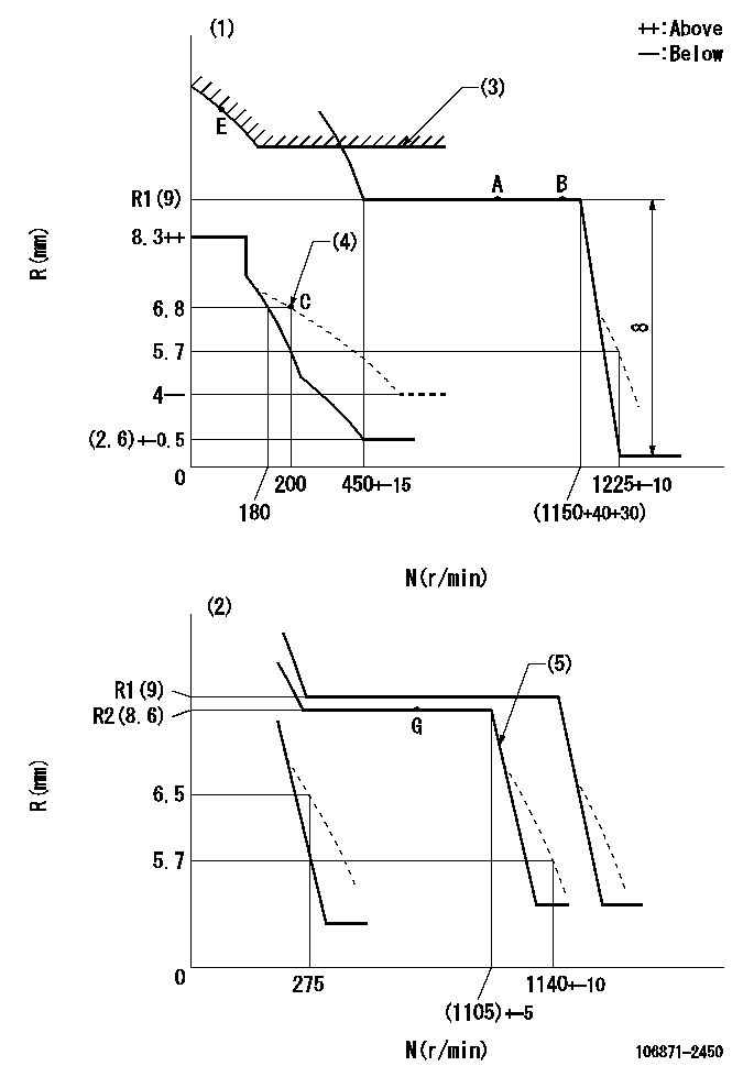
N:Pump speed
R:Rack position (mm)
(1)Adjust with speed control lever at full position (minimum-maximum speed specification)
(2)Adjust with the load control lever in the full position (variable speed specification).
(3)Excess fuel setting for starting: SXL
(4)Damper spring setting
(5)When air cylinder is operating.
----------
SXL=R1(9)+3+2.8mm
----------
----------
SXL=R1(9)+3+2.8mm
----------
Speed control lever angle
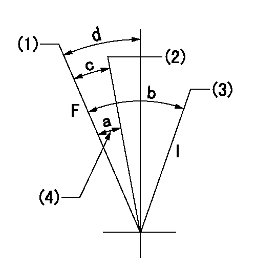
F:Full speed
I:Idle
(1)Pump speed = aa
(2)Pump speed = bb
(3)Pump speed cc
(4)Possible adjusting range
----------
aa=(1150)r/min bb=(1105)r/min cc=275r/min
----------
a=3deg b=(21deg)+-5deg c=3deg+-5deg d=9deg+-5deg
----------
aa=(1150)r/min bb=(1105)r/min cc=275r/min
----------
a=3deg b=(21deg)+-5deg c=3deg+-5deg d=9deg+-5deg
0000000901
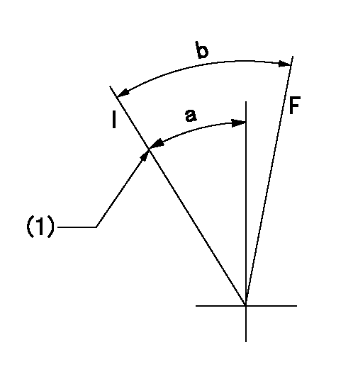
F:Full load
I:Idle
(1)Stopper bolt setting
----------
----------
a=(23.5deg)+-5deg b=23deg+-5deg
----------
----------
a=(23.5deg)+-5deg b=23deg+-5deg
Stop lever angle

N:Pump normal
S:Stop the pump.
----------
----------
a=56deg+-5deg b=64deg+-5deg
----------
----------
a=56deg+-5deg b=64deg+-5deg
0000001501 MICRO SWITCH
Adjustment of the micro-switch
Adjust the bolt to obtain the following lever position when the micro-switch is ON.
(1)Speed N1
(2)Rack position Ra
----------
N1=325+-5r/min Ra=6.3mm
----------
----------
N1=325+-5r/min Ra=6.3mm
----------
0000001601 2-STAGE CHANGEOVER DEVICE

RFD governor 2 stage changeover mechanism adjustment outline
(A) Bolt
(B) bolt
(c) Nut
(D) Return spring
(E) Bolt
(F) Bolt
(G) Screw
(H) Bolt
(I) Load lever
(J) Speed lever
(K) Air cylinder
(M Air inlet
Figure 1 is only for reference. Lever shape, etc, may vary.
1. Minimum-maximum speed specification adjustment (when running)
(a) Without applying air to the air cylinder, loosen bolts (A) and (B).
(1)High speed return L setting
(a) In the speed range Nf~Nf - 300r/min, adjust using the speed adjusting bolt to determine the temporary beginning of high speed control speed.
(b) Determine the rack position in the vicinity of Rf using the full load lever.
(c) Increase speed and confirm return distance L.
(d) Adjust using the tension lever bolt to obtain L.
(2)Setting full load rack position Rf
(a) Move the load control lever to the full side.
(b) Adjust the full load adjusting bolt so that Rf can be obtained, then fix.
(3)Setting the beginning of high speed operation Nf
(a) Adjust using bolt (E) so that Nf can be obtained, and then fix.
(4)Idle control setting (Re, Ni, Rc)
(a) Set the speed at Ns + 200r/min and move the load control lever to the idle side.
(b) Fix the lever in the position where Re can be obtained.
(c) Next, decrease speed to Ni and screw in the idle spring.
(d) Adjust to obtain rack position Ri.
(e) Increase the speed and after confirming that the rack position is Re at Ns, set the speed at 0.
(f) Confirm protrusion position Rc at idle.
(5)Damper spring adjustment
(a) Increase speed and set the speed at the rack position Rd - 0.1 mm
(b) Set using the damper spring so that the rack position Rd can be obtained.
(c) When Rd is not specified, Rd = Ri - 0.5 mm.
(6)High speed droop confirmation
(a) Return the load control lever to the full load lever position.
(b) Increase the speed and confirm that Rf can be obtained at Nf r/min.
(c) Confirm that speed is Nh at rack position Rh.
2. Variable speed specification adjustment (at operation)
(a) Remove return spring (D).
(b) Apply air pressure of 245~294 kPa {2.5~3 kg/cm2} to the air cylinder.
(c) Perform the following adjustment in this condition.
(1)Setting full load rack position Rf'
(a) Pull the load lever to the idle side.
(b) Obtain rack position Rf' using the nut (C). (Pump speed is Nf'-50 r/min.)
(2)Setting full speed Nf'
(a) Adjust using bolt (B) so that Nf can be obtained, and then fix.
(3)Low speed side setting
(a) At 350r/min, set bolt (F) at beginning of governor operation position, then fix.
3. Bolt (A) adjustment
(1)Install return spring (D) and perform the adjustments below at air pressure 0.
(a) Set at speed Nf using bolt (E).
(b) Screw in bolt (A).
(c) Screw in 1 more turn from the speed lever contact position
(d) Fix bolt (A).
(e) At this time confirm that the air cylinder's shaft moves approximately 1 mm towards the governor.
4. Lever operation confirmation using the air cylinder
(1)Apply 588 kPa {6 kg/cm2} air pressure to the air cylinder.
(2)Confirm that the cylinder piston is moved 50 mm by the spring (D).
----------
----------
----------
----------
Information:
TECHNICAL INFORMATION BULLETIN March 05, 2003
Articulated Truck
Cold Planer
Landfill Compactor
Excavator
Motor Grader
Off-Highway Truck/Tractor
Quarry Truck
Track-Type Tractor
Underground Articulated Truck
Wheel Loader
Wheel Tractor
Wheel Tractor-Scraper D30C (05A)
PM-565 (3TK)
PM-565B (8GS)
836 (7FR)
5110B (AAA)
24H (7KK)
69D (9SS, 9XS)
73D (1GW)
769D (BBB, 5SS, 5TR)
773D (7ER, 7CS)
771D (BCA, 6JR, 6YS)
775D (6KR, 8AS)
D10R (3KR)
D9R (ABK, ACL, 7TL, 8BL)
AD40 II (1YZ)
AD45 (BKZ)
AE40 II (BLW, 1ZZ)
988F II (2ZR)
990 II (4FR)
834B (7BR)
844 (2KZ)
631E II (1AB1446-Up, 1NB)
631E (1AB1-1445)
631G (AWK)
633E II (2PS)
637E II (1FB532-Up)
637E (1FB1-531)
637G (AXT)
651E (4YR)
657E (5YR, 6PR, 6TR, 7KR)
Component Code: 1901SUBJECT: Flashing New Software When Electronic Control Module (ECM) or Injectors Are Replaced
PROBLEM:
There have been dealer reports of engine ECMs locking up when new software is being installed. Dealer staff may see a message on the service tool such as: "The ECM is not responding to the service tool. Error code 864256". The flashing will typically hang up after 88% complete. When you reconnect, ET will not be able to communicate. Messages you typically get: "The communication adapter was unable to connect to the ATA data link. Error # 441. The requested protocol is not compatible with an existing datalink." You may also see: "The software file and the ECM are not compatible. Process aborted ? Error Code: 147456."
The two new software part numbers are:
222-XXXX (needed when a 172-0802 ECM is replaced by a 156-7156 ECM)
214-YYYY (needed when new-style injectors are installed)
SOLUTION:
If you are considering performing Product Support Program PS50424 on one of the above-listed machines, you may want to delay the program until new software is released. New software will be released in the near future to resolve this issue. Once the flashfiles are in SIS Web, a follow-up TIB will announce the new software?s availability.
On machine engines that have an older ECM that fails (145-7808 or 172-0802), the current 156-7172 production ECM will be needed for parts service. This will require using one of the 222-XXXX flashfiles. To minimize the possibility of locking-up the ECM, the dealer service staff can do one of the following:
Flash the ECM before traveling to the job site. This will require a By-Pass harness.
Flash the ECM on the engine. A By-Pass harness is recommended. If a By-Pass harness is used, disconnect the machine wiring harness before flashing the engine ECM. Dealers report that this method reduces the number of lock-ups.
If the dealer does not have a By-Pass harness, one will have to be purchased or assembled. If a new 129-2018 Wiring Harness Assembly (By-Pass) is purchased, modifications are necessary. Instructions on how to modify a By-Pass harness (Method 1: Modify a By-Pass Harness) and assemble a By-Pass harness (Method 2: Assemble a By-Pass Harness) appear later in this TIB.
Note: When flashing engine ECMs, always download the file from SIS Web to the computer?s hard drive. The service person should then upload (flash) to the ECM from the computer?s hard drive. For a listing of all models affected and the current software, refer to REHS1385-02, "Introduction of New 3408E and 3412E Hydraulic Electronic Unit Injectors".
Method 1: Modify a By-Pass Harness
When flashing an on-engine ECM with the current files, Caterpillar recommends the use
Have questions with 106871-2450?
Group cross 106871-2450 ZEXEL
Mitsubishi
106871-2450
9 400 618 090
ME066505
INJECTION-PUMP ASSEMBLY
8DC8
8DC8