Information injection-pump assembly
ZEXEL
106871-2041
1068712041
MITSUBISHI
ME066029
me066029

Rating:
Cross reference number
ZEXEL
106871-2041
1068712041
MITSUBISHI
ME066029
me066029
Zexel num
Bosch num
Firm num
Name
Calibration Data:
Adjustment conditions
Test oil
1404 Test oil ISO4113 or {SAEJ967d}
1404 Test oil ISO4113 or {SAEJ967d}
Test oil temperature
degC
40
40
45
Nozzle and nozzle holder
105780-8140
Bosch type code
EF8511/9A
Nozzle
105780-0000
Bosch type code
DN12SD12T
Nozzle holder
105780-2080
Bosch type code
EF8511/9
Opening pressure
MPa
17.2
Opening pressure
kgf/cm2
175
Injection pipe
Outer diameter - inner diameter - length (mm) mm 8-3-600
Outer diameter - inner diameter - length (mm) mm 8-3-600
Overflow valve
134424-1120
Overflow valve opening pressure
kPa
157
123
191
Overflow valve opening pressure
kgf/cm2
1.6
1.25
1.95
Tester oil delivery pressure
kPa
157
157
157
Tester oil delivery pressure
kgf/cm2
1.6
1.6
1.6
Direction of rotation (viewed from drive side)
Right R
Right R
Injection timing adjustment
Direction of rotation (viewed from drive side)
Right R
Right R
Injection order
1-2-7-3-
4-5-6-8
Pre-stroke
mm
4.8
4.75
4.85
Beginning of injection position
Governor side NO.1
Governor side NO.1
Difference between angles 1
Cyl.1-2 deg. 45 44.5 45.5
Cyl.1-2 deg. 45 44.5 45.5
Difference between angles 2
Cal 1-7 deg. 90 89.5 90.5
Cal 1-7 deg. 90 89.5 90.5
Difference between angles 3
Cal 1-3 deg. 135 134.5 135.5
Cal 1-3 deg. 135 134.5 135.5
Difference between angles 4
Cal 1-4 deg. 180 179.5 180.5
Cal 1-4 deg. 180 179.5 180.5
Difference between angles 5
Cal 1-5 deg. 225 224.5 225.5
Cal 1-5 deg. 225 224.5 225.5
Difference between angles 6
Cal 1-6 deg. 270 269.5 270.5
Cal 1-6 deg. 270 269.5 270.5
Difference between angles 7
Cal 1-8 deg. 315 314.5 315.5
Cal 1-8 deg. 315 314.5 315.5
Injection quantity adjustment
Adjusting point
A
Rack position
9.3
Pump speed
r/min
1100
1100
1100
Average injection quantity
mm3/st.
106
101.4
110.6
Max. variation between cylinders
%
0
-4
4
Fixing the lever
*
Injection quantity adjustment_02
Adjusting point
B
Rack position
9.3
Pump speed
r/min
700
700
700
Average injection quantity
mm3/st.
96
92.5
99.5
Max. variation between cylinders
%
0
-3
3
Basic
*
Fixing the lever
*
Injection quantity adjustment_03
Adjusting point
C
Rack position
6.5+-0.5
Pump speed
r/min
200
200
200
Average injection quantity
mm3/st.
15
12.4
17.6
Max. variation between cylinders
%
0
-15
15
Fixing the rack
*
Injection quantity adjustment_04
Adjusting point
D
Rack position
11.5+-0.
5
Pump speed
r/min
100
100
100
Average injection quantity
mm3/st.
123
123
Fixing the lever
*
Remarks
After startup boost setting
After startup boost setting
Timer adjustment
Pump speed
r/min
850+-0.5
Advance angle
deg.
0
0
0
Remarks
Start
Start
Timer adjustment_02
Pump speed
r/min
900
Advance angle
deg.
0.8
0.3
1.3
Timer adjustment_03
Pump speed
r/min
1000
Advance angle
deg.
2.1
1.6
2.6
Timer adjustment_04
Pump speed
r/min
1150
Advance angle
deg.
5.5
4.9
6.1
Remarks
Finish
Finish
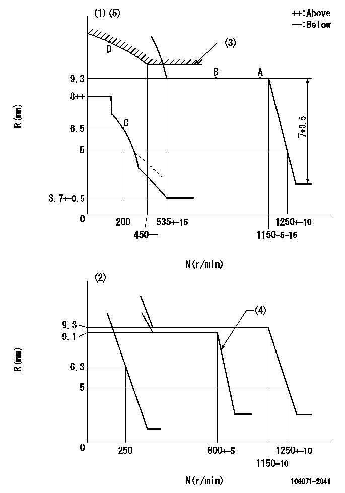
Test data Ex:
Governor adjustment

N:Pump speed
R:Rack position (mm)
(1)Adjust with speed control lever at full position (minimum-maximum speed specification)
(2)Adjust with the load control lever in the full position (variable speed specification).
(3)Excess fuel setting for starting: SXL
(4)When air cylinder is operating.
(5)Beginning of damper spring operation: DL
----------
SXL=9.3+0.2mm DL=5-0.2mm
----------
----------
SXL=9.3+0.2mm DL=5-0.2mm
----------
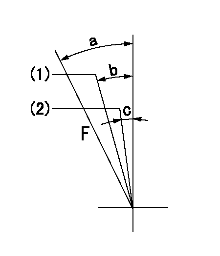
Speed control lever angle

F:Full speed
(1)Set the pump speed at aa
(2)Set the pump speed at bb.
----------
aa=800r/min bb=250r/min
----------
a=22deg+-5deg b=12.5deg+-5deg c=3deg+-5deg
----------
aa=800r/min bb=250r/min
----------
a=22deg+-5deg b=12.5deg+-5deg c=3deg+-5deg
0000000901

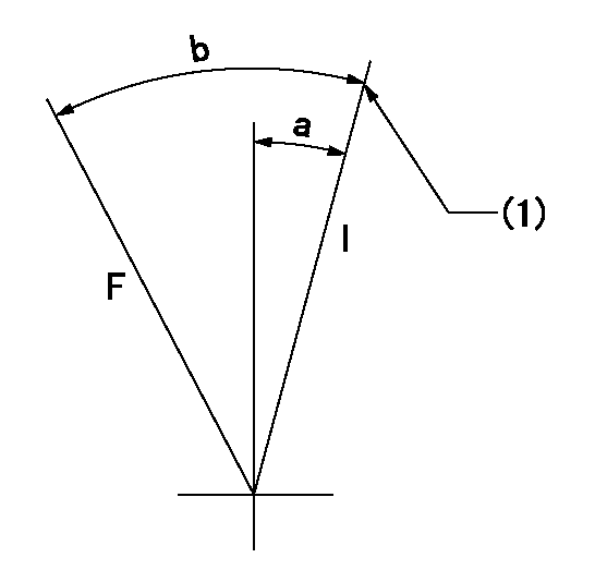
F:Full load
I:Idle
(1)Stopper bolt setting
----------
----------
a=10deg+-5deg b=22deg+-3deg
----------
----------
a=10deg+-5deg b=22deg+-3deg
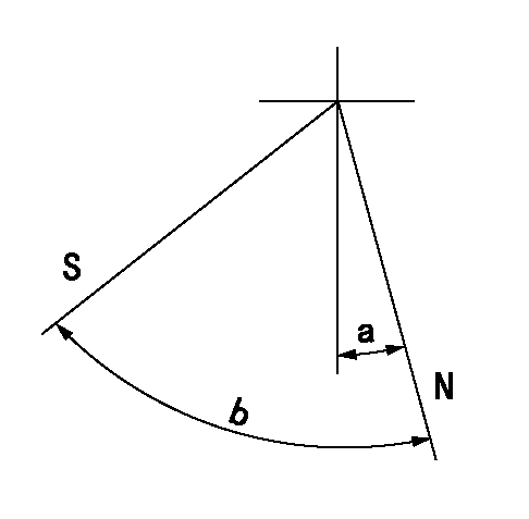
Stop lever angle

N:Pump normal
S:Stop the pump.
----------
----------
a=10deg+-5deg b=64deg+-5deg
----------
----------
a=10deg+-5deg b=64deg+-5deg
0000001501 MICRO SWITCH
Adjustment of the micro-switch
Adjust the bolt to obtain the following lever position when the micro-switch is ON.
(1)Speed N1
(2)Rack position Ra
----------
N1=310r/min Ra=6.5mm
----------
----------
N1=310r/min Ra=6.5mm
----------
0000001601 2-STAGE CHANGEOVER DEVICE

RFD governor 2 stage changeover mechanism adjustment outline
(A) Bolt
(B) bolt
(c) Nut
(D) Return spring
(E) Bolt
(F) Bolt
(G) Screw
(H) Bolt
(I) Load lever
(J) Speed lever
(K) Air cylinder
(M Air inlet
Figure 1 is only for reference. Lever shape, etc, may vary.
1. Minimum-maximum speed specification adjustment (when running)
(a) Without applying air to the air cylinder, loosen bolts (A) and (B).
(1)High speed return L setting
(a) In the speed range Nf~Nf - 300r/min, adjust using the speed adjusting bolt to determine the temporary beginning of high speed control speed.
(b) Determine the rack position in the vicinity of Rf using the full load lever.
(c) Increase speed and confirm return distance L.
(d) Adjust using the tension lever bolt to obtain L.
(2)Setting full load rack position Rf
(a) Move the load control lever to the full side.
(b) Adjust the full load adjusting bolt so that Rf can be obtained, then fix.
(3)Setting the beginning of high speed operation Nf
(a) Adjust using bolt (E) so that Nf can be obtained, and then fix.
(4)Idle control setting (Re, Ni, Rc)
(a) Set the speed at Ns + 200r/min and move the load control lever to the idle side.
(b) Fix the lever in the position where Re can be obtained.
(c) Next, decrease speed to Ni and screw in the idle spring.
(d) Adjust to obtain rack position Ri.
(e) Increase the speed and after confirming that the rack position is Re at Ns, set the speed at 0.
(f) Confirm protrusion position Rc at idle.
(5)Damper spring adjustment
(a) Increase speed and set the speed at the rack position Rd - 0.1 mm
(b) Set using the damper spring so that the rack position Rd can be obtained.
(c) When Rd is not specified, Rd = Ri - 0.5 mm.
(6)High speed droop confirmation
(a) Return the load control lever to the full load lever position.
(b) Increase the speed and confirm that Rf can be obtained at Nf r/min.
(c) Confirm that speed is Nh at rack position Rh.
2. Variable speed specification adjustment (at operation)
(a) Remove return spring (D).
(b) Apply air pressure of 245~294 kPa {2.5~3 kg/cm2} to the air cylinder.
(c) Perform the following adjustment in this condition.
(1)Setting full load rack position Rf'
(a) Pull the load lever to the idle side.
(b) Obtain rack position Rf' using the nut (C). (Pump speed is Nf'-50 r/min.)
(2)Setting full speed Nf'
(a) Adjust using bolt (B) so that Nf can be obtained, and then fix.
(3)Low speed side setting
(a) At 350r/min, set bolt (F) at beginning of governor operation position, then fix.
3. Bolt (A) adjustment
(1)Install return spring (D) and perform the adjustments below at air pressure 0.
(a) Set at speed Nf using bolt (E).
(b) Screw in bolt (A).
(c) Screw in 1 more turn from the speed lever contact position
(d) Fix bolt (A).
(e) At this time confirm that the air cylinder's shaft moves approximately 1 mm towards the governor.
4. Lever operation confirmation using the air cylinder
(1)Apply 588 kPa {6 kg/cm2} air pressure to the air cylinder.
(2)Confirm that the cylinder piston is moved 50 mm by the spring (D).
----------
----------
----------
----------
Information:
ACTION REQUIRED
After Failure:
1 - Update Engine Software, refer to UENR0611 Troubleshooting ? ECM Software ? Install, ensure to follow the steps to save the Engine Configuration data. Refer to the table in Image 1 to determine the correct engine software file to apply.
2 - Service CCB Filter and replace with new filter, refer to SEBU8727 Operation and Maintenance Manual ? Engine Crankcase Breather element ? Replace.
3 - Remove Diesel Particulate Filter, Refer to UENR0621 Disassembly and Assembly - Diesel Particulate Filter - Remove - Wall Flow Diesel Particulate Filter.
4 - Move the Diesel Particulate Filter Assembly to a suitable work surface.
5 - Refer to UENR0619 Specifications - Diesel Particulate Filter (Wall Flow Diesel Particulate Filter(DPF)), remove V Band Clamps (1)&(4), carefully split assembly and remove DPF Canister element.
6 - Using new DPF Kit Filter, reassemble the Diesel Particulate Filter Assembly noting the alignment marks previously made in Step 3, refer to UENR0619 Specifications - Diesel Particulate Filter (Wall Flow Diesel Particulate Filter(DPF)).
7 - Reinstall the Diesel Particulate Filter assembly, Refer to UENR0621 Disassembly and Assembly - Diesel Particulate Filter - Install - Wall Flow Diesel Particulate Filter.
8 - As the DPF has been replaced, ensure the ?DPF Replacement Reset? procedure is performed using CAT ET, refer to UENR0611 Troubleshooting - Service Tool Features - Components Replacement Resets.
Image1
SERVICE CLAIM ALLOWANCES
Product smu/age whichever comes first Caterpillar Dealer Suggested Customer Suggested
Parts % Labor Hrs% Parts % Labor Hrs% Parts % Labor Hrs%
*******Group 1*******
0-3000 hrs,
0-60 mo 100.0% 100.0% 0.0% 0.0% 0.0% 0.0%
This is a 6.0-hour job for Group 1
Product smu/age whichever comes first Caterpillar Dealer Suggested Customer Suggested
Parts % Labor Hrs% Parts % Labor Hrs% Parts % Labor Hrs%
*******Group 2*******
0-3000 hrs,
0-60 mo 100.0% 100.0% 0.0% 0.0% 0.0% 0.0%
This is a 6.0-hour job for Group 2
PARTS DISPOSITION
Handle the parts in accordance with your Warranty Bulletin on warranty parts handling.