Information injection-pump assembly
BOSCH
9 400 618 077
9400618077
ZEXEL
106871-1202
1068711202
ISUZU
1156032001
1156032001

Rating:
Service parts 106871-1202 INJECTION-PUMP ASSEMBLY:
1.
_
6.
COUPLING PLATE
7.
COUPLING PLATE
8.
_
9.
_
11.
Nozzle and Holder
12.
Open Pre:MPa(Kqf/cm2)
15.7{160}/22.1{225}
15.
NOZZLE SET
Include in #1:
106871-1202
as INJECTION-PUMP ASSEMBLY
Cross reference number
BOSCH
9 400 618 077
9400618077
ZEXEL
106871-1202
1068711202
ISUZU
1156032001
1156032001
Zexel num
Bosch num
Firm num
Name
106871-1202
9 400 618 077
1156032001 ISUZU
INJECTION-PUMP ASSEMBLY
K 14CD INJECTION PUMP ASSY PE8P PE
K 14CD INJECTION PUMP ASSY PE8P PE
Calibration Data:
Adjustment conditions
Test oil
1404 Test oil ISO4113 or {SAEJ967d}
1404 Test oil ISO4113 or {SAEJ967d}
Test oil temperature
degC
40
40
45
Nozzle and nozzle holder
105780-8250
Bosch type code
1 688 901 101
Nozzle
105780-0120
Bosch type code
1 688 901 990
Nozzle holder
105780-2190
Opening pressure
MPa
20.7
Opening pressure
kgf/cm2
211
Injection pipe
Outer diameter - inner diameter - length (mm) mm 8-3-600
Outer diameter - inner diameter - length (mm) mm 8-3-600
Overflow valve
134424-4320
Overflow valve opening pressure
kPa
255
221
289
Overflow valve opening pressure
kgf/cm2
2.6
2.25
2.95
Tester oil delivery pressure
kPa
255
255
255
Tester oil delivery pressure
kgf/cm2
2.6
2.6
2.6
Direction of rotation (viewed from drive side)
Right R
Right R
Injection timing adjustment
Direction of rotation (viewed from drive side)
Right R
Right R
Injection order
1-8-7-3-
6-5-4-2
Pre-stroke
mm
5.5
5.47
5.53
Rack position
Point A R=A
Point A R=A
Beginning of injection position
Governor side NO.1
Governor side NO.1
Difference between angles 1
Cal 1-8 deg. 45 44.75 45.25
Cal 1-8 deg. 45 44.75 45.25
Difference between angles 2
Cal 1-7 deg. 90 89.75 90.25
Cal 1-7 deg. 90 89.75 90.25
Difference between angles 3
Cal 1-3 deg. 135 134.75 135.25
Cal 1-3 deg. 135 134.75 135.25
Difference between angles 4
Cal 1-6 deg. 180 179.75 180.25
Cal 1-6 deg. 180 179.75 180.25
Difference between angles 5
Cal 1-5 deg. 225 224.75 225.25
Cal 1-5 deg. 225 224.75 225.25
Difference between angles 6
Cal 1-4 deg. 270 269.75 270.25
Cal 1-4 deg. 270 269.75 270.25
Difference between angles 7
Cyl.1-2 deg. 315 314.75 315.25
Cyl.1-2 deg. 315 314.75 315.25
Injection quantity adjustment
Adjusting point
-
Rack position
10.7
Pump speed
r/min
800
800
800
Average injection quantity
mm3/st.
121
119.4
122.6
Max. variation between cylinders
%
0
-3
3
Basic
*
Fixing the rack
*
Standard for adjustment of the maximum variation between cylinders
*
Injection quantity adjustment_02
Adjusting point
Z
Rack position
6.5+-0.5
Pump speed
r/min
420
420
420
Average injection quantity
mm3/st.
13.5
11.5
15.5
Max. variation between cylinders
%
0
-13
13
Fixing the rack
*
Standard for adjustment of the maximum variation between cylinders
*
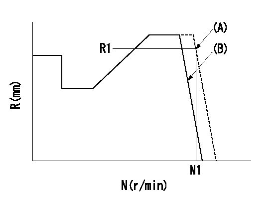
Injection quantity adjustment_03
Adjusting point
A
Rack position
R1(10.7)
Pump speed
r/min
800
800
800
Average injection quantity
mm3/st.
121
120
122
Basic
*
Fixing the lever
*
Injection quantity adjustment_04
Adjusting point
B
Rack position
R1+0.9
Pump speed
r/min
1150
1150
1150
Average injection quantity
mm3/st.
122
118
126
Fixing the lever
*
Timer adjustment
Pump speed
r/min
[N1+50]-
-
Advance angle
deg.
0
0
0
Remarks
Start
Start
Timer adjustment_02
Pump speed
r/min
N1
Advance angle
deg.
0
0
0
Remarks
Measure the actual speed.
Measure the actual speed.
Timer adjustment_03
Pump speed
r/min
-
Advance angle
deg.
2
1.5
2.5
Remarks
Measure the actual speed, stop
Measure the actual speed, stop
Test data Ex:
Governor adjustment
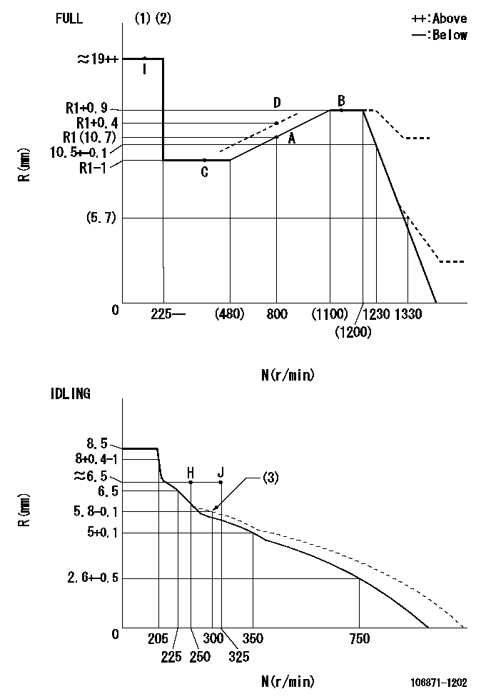
N:Pump speed
R:Rack position (mm)
(1)Torque cam stamping: T1
(2)Tolerance for racks not indicated: +-0.05mm.
(3)Damper spring setting
----------
T1=AC89
----------
----------
T1=AC89
----------
Speed control lever angle

F:Full speed
I:Idle
(1)Use the pin at R = aa
(2)Stopper bolt setting
----------
aa=55mm
----------
a=20deg+-5deg b=35deg+-3deg
----------
aa=55mm
----------
a=20deg+-5deg b=35deg+-3deg
Stop lever angle
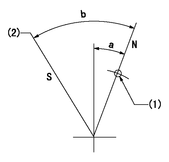
N:Pump normal
S:Stop the pump.
(1)Use the pin at R = aa
(2)Set the stopper bolt so that speed = bb and rack position = cc. (Confirm non-injection.)
----------
aa=40mm bb=0r/min cc=1.5+-0.3mm
----------
a=20deg+-5deg b=43deg+-5deg
----------
aa=40mm bb=0r/min cc=1.5+-0.3mm
----------
a=20deg+-5deg b=43deg+-5deg
0000001501 AIR CYLINDER
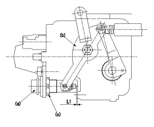
(a) Air cylinder
(b) Speed lever
(c) Lock nut
1. Air cylinder adjustment procedure
(1)Fix the speed lever (b) at the idle side.
(2)Screw in the air cylinder (a)
(3)Set the clearance between the speed lever (b) and the air cylinder (a) to approximately L1.
----------
L1=1mm
----------
----------
L1=1mm
----------
0000001601 TAMPER PROOF
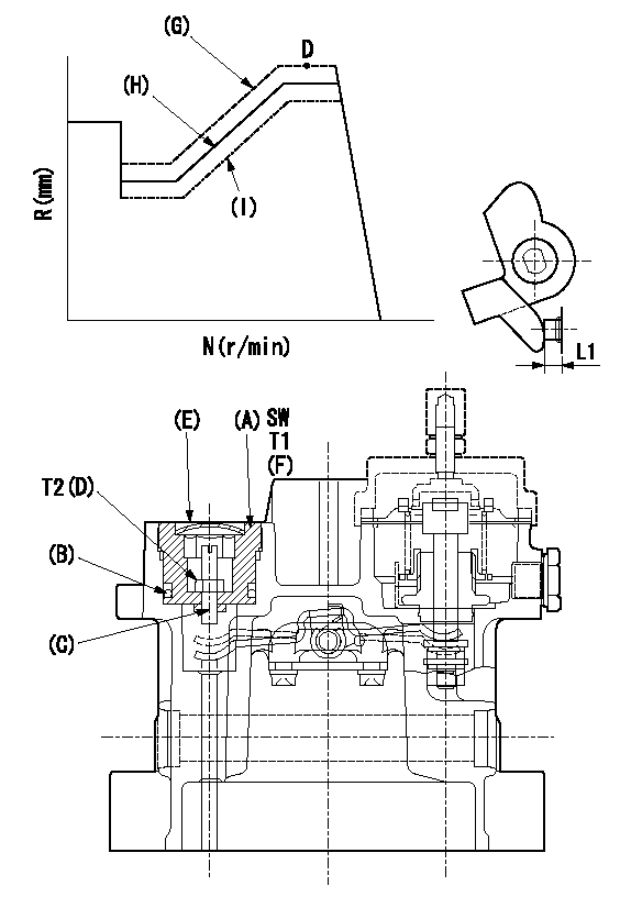
SW:Inner hexagonal SW14
(F): Apply thread lock adhesive .
(G): Full tamper proof
(H): Full boost (Full rack)
(I): 0 boost
1. Mount (C) and (D) after adjusting the boost compensator.
2. Back off the load lever set screw L1 from the end face of the governor housing..
3. Apply boost pressure and set the full load at tamper set position point aa to obtain N1, Q1 and Ra using the screw C.
4. Fix using the nut (D).
5. Next, after adjusting the stop lever, confirm the point aa.
6. Reset the load lever to the full boost rack.
7. After completion of setting, seal using the plug (E).
----------
L1=6+1mm N1=800r/min Ra=R1(10.7)+0.4mm Q1=103+-1.6mm3/st aa=D
----------
T1=53.9~73.5N-m(5.5~7.5Kgf-m) T2=2.94~4.41N-m(0.3~0.45Kgf-m)
----------
L1=6+1mm N1=800r/min Ra=R1(10.7)+0.4mm Q1=103+-1.6mm3/st aa=D
----------
T1=53.9~73.5N-m(5.5~7.5Kgf-m) T2=2.94~4.41N-m(0.3~0.45Kgf-m)
0000001701 TAMPER PROOF
(A): Rotation tamper proof
(B): Full-speed setting
1. Back off the full-speed set bolt.
2. Confirm that the tamper setting position is N1, R1, Q1.
3. At that time, record the angle of the speed lever.
4. After confirming the above setting, set full speed.
----------
N1=(1420)r/min R1=5.7+-0.1mm Q1=-
----------
----------
N1=(1420)r/min R1=5.7+-0.1mm Q1=-
----------
Timing setting

(1)Pump vertical direction
(2)Position of "Z" mark at the No 1 cylinder's beginning of injection (governor side)
(3)B.T.D.C.: aa
(4)-
----------
aa=10deg
----------
a=(170deg)
----------
aa=10deg
----------
a=(170deg)
Information:
PARTS NEEDED
Qty
Part Number Description
1 4716029 MTG GP-INJECTOR (After Failure Only)
1 5548955 DEF SOFTWARE
1 ENGSOFTWARE ENGINE SOFTWARE
In order to allow equitable parts availability to all participating dealers, please limit your initial parts order to not exceed 25% of dealership population. This is an initial order recommendation only, and the ultimate responsibility for ordering the total number of parts needed to satisfy the program lies with the dealer.
ACTION REQUIRED
New DEF System software is available that reduces the risk of an internal DEF injector leak by improved temperature management. Please update the DEF system software at the next opportunity.
Ensure that all adjustments and repairs that are carried out to the Diesel Emission Fluid (DEF) system are performed by authorized personnel that have the correct training. Before beginning ANY work on the DEF system, refer to Operations and Maintenance Manual, "General Hazard" for safety information.
Before Failure:
Check that the engine software is the latest version before updating the DEF pump software.
If the engine software is not the latest version, update the Engine Software first.
If needed, update the engine software with the latest available in SIS WEB.
Flash the DEF Pump ECM with the software listed in the Parts Needed or latest available in SIS Web.
After Failure:
Ensure the appropriate steps have been followed when diagnosing a DEF injector failure. Refer to UENR0662.
If it is determined that replacement of DEF injector is required, refer to Disassembly and Assembly Manual - Diesel Fluid Injector - Remove and install.
After the DEF injector has been replaced, perform the DEF system software update as detailed in the "Before Failure" section above.
SERVICE CLAIM ALLOWANCES
Product smu/age whichever comes first Caterpillar Dealer Suggested Customer Suggested
Parts % Labor Hrs% Parts % Labor Hrs% Parts % Labor Hrs%
0-5000 hrs,
0-60 mo 100.0% 100.0% 0.0% 0.0% 0.0% 0.0%
This is a 0.5-hour job
An additional 1.5 hours is allowed for After failure.
PARTS DISPOSITION
Handle the parts in accordance with your Warranty Bulletin on warranty parts handling.
Have questions with 106871-1202?
Group cross 106871-1202 ZEXEL
Isuzu
Isuzu
106871-1202
9 400 618 077
1156032001
INJECTION-PUMP ASSEMBLY