Information injection-pump assembly
ZEXEL
106871-1121
1068711121
ISUZU
1156029840
1156029840
Rating:
Cross reference number
ZEXEL
106871-1121
1068711121
ISUZU
1156029840
1156029840
Zexel num
Bosch num
Firm num
Name
Calibration Data:
Adjustment conditions
Test oil
1404 Test oil ISO4113 or {SAEJ967d}
1404 Test oil ISO4113 or {SAEJ967d}
Test oil temperature
degC
40
40
45
Nozzle and nozzle holder
105780-8250
Bosch type code
1 688 901 101
Nozzle
105780-0120
Bosch type code
1 688 901 990
Nozzle holder
105780-2190
Opening pressure
MPa
20.7
Opening pressure
kgf/cm2
211
Injection pipe
Outer diameter - inner diameter - length (mm) mm 8-3-600
Outer diameter - inner diameter - length (mm) mm 8-3-600
Overflow valve
134424-4320
Overflow valve opening pressure
kPa
255
221
289
Overflow valve opening pressure
kgf/cm2
2.6
2.25
2.95
Tester oil delivery pressure
kPa
255
255
255
Tester oil delivery pressure
kgf/cm2
2.6
2.6
2.6
Direction of rotation (viewed from drive side)
Right R
Right R
Injection timing adjustment
Direction of rotation (viewed from drive side)
Right R
Right R
Injection order
1-8-7-3-
6-5-4-2
Pre-stroke
mm
5.5
5.47
5.53
Rack position
Point A R=A
Point A R=A
Beginning of injection position
Governor side NO.1
Governor side NO.1
Difference between angles 1
Cal 1-8 deg. 45 44.75 45.25
Cal 1-8 deg. 45 44.75 45.25
Difference between angles 2
Cal 1-7 deg. 90 89.75 90.25
Cal 1-7 deg. 90 89.75 90.25
Difference between angles 3
Cal 1-3 deg. 135 134.75 135.25
Cal 1-3 deg. 135 134.75 135.25
Difference between angles 4
Cal 1-6 deg. 180 179.75 180.25
Cal 1-6 deg. 180 179.75 180.25
Difference between angles 5
Cal 1-5 deg. 225 224.75 225.25
Cal 1-5 deg. 225 224.75 225.25
Difference between angles 6
Cal 1-4 deg. 270 269.75 270.25
Cal 1-4 deg. 270 269.75 270.25
Difference between angles 7
Cyl.1-2 deg. 315 314.75 315.25
Cyl.1-2 deg. 315 314.75 315.25
Injection quantity adjustment
Adjusting point
-
Rack position
10.3
Pump speed
r/min
700
700
700
Average injection quantity
mm3/st.
109
107.4
110.6
Max. variation between cylinders
%
0
-3
3
Basic
*
Fixing the rack
*
Standard for adjustment of the maximum variation between cylinders
*
Injection quantity adjustment_02
Adjusting point
Z
Rack position
6.5+-0.5
Pump speed
r/min
420
420
420
Average injection quantity
mm3/st.
13.5
11.5
15.5
Max. variation between cylinders
%
0
-13
13
Fixing the rack
*
Standard for adjustment of the maximum variation between cylinders
*
Injection quantity adjustment_03
Adjusting point
A
Rack position
R1(10.3)
Pump speed
r/min
700
700
700
Average injection quantity
mm3/st.
109
108
110
Basic
*
Fixing the lever
*
Injection quantity adjustment_04
Adjusting point
B
Rack position
R1+1.2
Pump speed
r/min
1150
1150
1150
Average injection quantity
mm3/st.
115
111
119
Fixing the lever
*
Test data Ex:
Governor adjustment
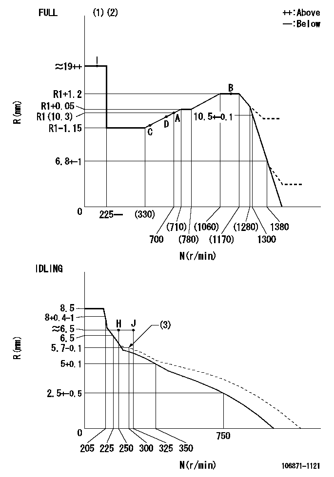
N:Pump speed
R:Rack position (mm)
(1)Torque cam stamping: T1
(2)Tolerance for racks not indicated: +-0.05mm.
(3)Damper spring setting
----------
T1=AC67
----------
----------
T1=AC67
----------
Timer adjustment

(1)Adjusting range
(2)Step response time
(N): Speed of the pump
(L): Load
(theta) Advance angle
(Srd1) Step response time 1
(Srd2) Step response time 2
1. Adjusting conditions for the variable timer
(1)Adjust the clearance between the pickup and the protrusion to L.
----------
L=1-0.2mm N2=800r/min C2=(8)deg t1=1.5--sec. t2=1.5--sec.
----------
N1=950++r/min P1=0kPa(0kgf/cm2) P2=392kPa(4kgf/cm2) C1=8+-0.3deg R01=0/4load R02=4/4load
----------
L=1-0.2mm N2=800r/min C2=(8)deg t1=1.5--sec. t2=1.5--sec.
----------
N1=950++r/min P1=0kPa(0kgf/cm2) P2=392kPa(4kgf/cm2) C1=8+-0.3deg R01=0/4load R02=4/4load
Speed control lever angle

F:Full speed
I:Idle
(1)Use the pin at R = aa
(2)Stopper bolt set position 'H'
----------
aa=42.5mm
----------
a=20deg+-5deg b=33deg+-3deg
----------
aa=42.5mm
----------
a=20deg+-5deg b=33deg+-3deg
Stop lever angle
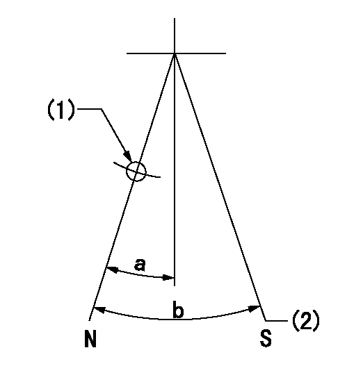
N:Pump normal
S:Stop the pump.
(1)Use the pin at R = aa
(2)Set the stopper bolt so that speed = bb and rack position = cc. (Confirm non-injection.)
----------
aa=37.5mm bb=0r/min cc=1.5+-0.3mm
----------
a=40deg+-5deg b=43deg+-5deg
----------
aa=37.5mm bb=0r/min cc=1.5+-0.3mm
----------
a=40deg+-5deg b=43deg+-5deg
0000001501 RACK SENSOR
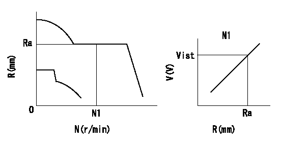
Rack sensor adjustment
1. Flange type rack sensor (rack sensor adjustment -5*20)
(1)These types of rack sensors do not need adjustment. Confirm the performance with the following procedures.
(2)Mount the rack sensor main body to the pump main body.
(3)Fix the pump lever at full.
(4)At supply voltage V1, pump speed N1 and rack position Ra, confirm that the amp's output voltage is Vist.
(5)Move the pump lever two or three times.
(6)Set again to full.
(7)Confirm that the amplifier output voltage is Vist.
(8)Fix the caution plate to the upper part of the rack sensor.
(For those without the caution plate instructions, make sure the nameplate of the rack sensor carries the "Don't hold here" caution.)
(9)Apply red paint to the rack sensor mounting bolts (2 places).
----------
V1=5+-0.01V N1=1150r/min Ra=R1(10.3)+1.2mm Vist=1.65+-0.14V
----------
----------
V1=5+-0.01V N1=1150r/min Ra=R1(10.3)+1.2mm Vist=1.65+-0.14V
----------
Timing setting

(1)Pump vertical direction
(2)Position of "Z" mark at the No 1 cylinder's beginning of injection (governor side)
(3)B.T.D.C.: aa
(4)-
----------
aa=4deg
----------
a=(180deg)
----------
aa=4deg
----------
a=(180deg)
Information:
ACTION REQUIRED
1. Refer to Special Instruction, REHS5023, "Replacing the Fuel Injection Pump on Certain C9.3 Engines". Replace the existing 375-5244 or early production 379-0150 common rail fuel injection pump with the new production 379-0150 common rail fuel injection pump and new gasket 6V-8260. Install a new 356-5214 fuel line from the common rail fuel injection pump to the fuel rail.
2. Refer to C9.3 Disassembly and Assembly, KENR8149 "Engines for Caterpillar Built Machines". Replace the prior 362-0770 Pressure Relief Valve with 415-4991 Pressure Relief Valve, and 228-7102 O-ring.
3. Refer to Service Magazine, SEPD1928, "An Improved Fuel Injection Pump Group Is Used on Certain C9.3 Machine Engines", in order to record the common rail fuel injection pump serial number. This serial number must be entered into the containment service letter claim story.
SERVICE CLAIM ALLOWANCES
Product smu/age whichever comes first Caterpillar Dealer Suggested Customer Suggested
Parts % Labor Hrs% Parts % Labor Hrs% Parts % Labor Hrs%
*******Group 1*******
0-5000 hrs,
0-48 mo 100.0% 100.0% 0.0% 0.0% 0.0% 0.0%
This is a 12.0-hour job for Group 1
Product smu/age whichever comes first Caterpillar Dealer Suggested Customer Suggested
Parts % Labor Hrs% Parts % Labor Hrs% Parts % Labor Hrs%
*******Group 2*******
0-5000 hrs,
0-48 mo 100.0% 100.0% 0.0% 0.0% 0.0% 0.0%
This is a 18.0-hour job for Group 2
Product smu/age whichever comes first Caterpillar Dealer Suggested Customer Suggested
Parts % Labor Hrs% Parts % Labor Hrs% Parts % Labor Hrs%
*******Group 3*******
0-5000 hrs,
0-48 mo 100.0% 100.0% 0.0% 0.0% 0.0% 0.0%
This is a 15.0-hour job for Group 3
PARTS DISPOSITION
Handle the parts in accordance with your Warranty Bulletin on warranty parts handling.