Information injection-pump assembly
ZEXEL
106871-1017
1068711017
ISUZU
1156014587
1156014587
Rating:
Cross reference number
ZEXEL
106871-1017
1068711017
ISUZU
1156014587
1156014587
Zexel num
Bosch num
Firm num
Name
Calibration Data:
Adjustment conditions
Test oil
1404 Test oil ISO4113 or {SAEJ967d}
1404 Test oil ISO4113 or {SAEJ967d}
Test oil temperature
degC
40
40
45
Nozzle and nozzle holder
105780-8140
Bosch type code
EF8511/9A
Nozzle
105780-0000
Bosch type code
DN12SD12T
Nozzle holder
105780-2080
Bosch type code
EF8511/9
Opening pressure
MPa
17.2
Opening pressure
kgf/cm2
175
Injection pipe
Outer diameter - inner diameter - length (mm) mm 8-3-600
Outer diameter - inner diameter - length (mm) mm 8-3-600
Overflow valve opening pressure
kPa
157
123
191
Overflow valve opening pressure
kgf/cm2
1.6
1.25
1.95
Tester oil delivery pressure
kPa
157
157
157
Tester oil delivery pressure
kgf/cm2
1.6
1.6
1.6
Direction of rotation (viewed from drive side)
Right R
Right R
Injection timing adjustment
Direction of rotation (viewed from drive side)
Right R
Right R
Injection order
1-8-7-3-
6-5-4-2
Pre-stroke
mm
4.2
4.17
4.23
Beginning of injection position
Governor side NO.1
Governor side NO.1
Difference between angles 1
Cal 1-8 deg. 45 44.75 45.25
Cal 1-8 deg. 45 44.75 45.25
Difference between angles 2
Cal 1-7 deg. 90 89.75 90.25
Cal 1-7 deg. 90 89.75 90.25
Difference between angles 3
Cal 1-3 deg. 135 134.75 135.25
Cal 1-3 deg. 135 134.75 135.25
Difference between angles 4
Cal 1-6 deg. 180 179.75 180.25
Cal 1-6 deg. 180 179.75 180.25
Difference between angles 5
Cal 1-5 deg. 225 224.75 225.25
Cal 1-5 deg. 225 224.75 225.25
Difference between angles 6
Cal 1-4 deg. 270 269.75 270.25
Cal 1-4 deg. 270 269.75 270.25
Difference between angles 7
Cyl.1-2 deg. 315 314.75 315.25
Cyl.1-2 deg. 315 314.75 315.25
Injection quantity adjustment
Adjusting point
A
Rack position
8.2
Pump speed
r/min
1200
1200
1200
Average injection quantity
mm3/st.
99.8
97.8
101.8
Max. variation between cylinders
%
0
-3
3
Fixing the lever
*
Boost pressure
kPa
30.7
30.7
Boost pressure
mmHg
230
230
Injection quantity adjustment_02
Adjusting point
B
Rack position
8.7
Pump speed
r/min
650
650
650
Average injection quantity
mm3/st.
109.2
107.7
110.7
Max. variation between cylinders
%
0
-2
2
Basic
*
Fixing the lever
*
Boost pressure
kPa
30.7
30.7
Boost pressure
mmHg
230
230
Injection quantity adjustment_03
Adjusting point
C
Rack position
5.5+-0.5
Pump speed
r/min
225
225
225
Average injection quantity
mm3/st.
8.8
7.4
10.2
Max. variation between cylinders
%
0
-13
13
Fixing the rack
*
Boost pressure
kPa
0
0
0
Boost pressure
mmHg
0
0
0
Injection quantity adjustment_04
Adjusting point
D
Rack position
-
Pump speed
r/min
150
150
150
Average injection quantity
mm3/st.
90
90
Fixing the lever
*
Boost pressure
kPa
0
0
0
Boost pressure
mmHg
0
0
0
Injection quantity adjustment_05
Adjusting point
E
Rack position
11.8+-0.
5
Pump speed
r/min
150
150
150
Average injection quantity
mm3/st.
141
141
151
Fixing the lever
*
Boost pressure
kPa
0
0
0
Boost pressure
mmHg
0
0
0
Remarks
Startup boost setting
Startup boost setting
Boost compensator adjustment
Pump speed
r/min
600
600
600
Rack position
7.7
Boost pressure
kPa
6.7
5.4
8
Boost pressure
mmHg
50
40
60
Boost compensator adjustment_02
Pump speed
r/min
600
600
600
Rack position
8.7
Boost pressure
kPa
17.3
17.3
17.3
Boost pressure
mmHg
130
130
130
Test data Ex:
Governor adjustment
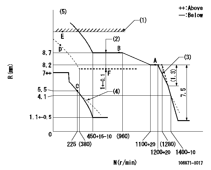
N:Pump speed
R:Rack position (mm)
(1)Excess fuel lever setting
(2)Boost compensator stroke
(3)Set the torque spring.
(4)Beginning of damper spring operation: DL
(5)Supply solenoid operating voltage DC24V and move the solenoid body so that the excess lever reaches the excess position at the solenoid's maximum stroke.
----------
DL=4.1-0.5mm
----------
----------
DL=4.1-0.5mm
----------
Timer adjustment

(1)Adjusting range
(2)Step response time
(N): Speed of the pump
(L): Load
(theta) Advance angle
(Srd1) Step response time 1
(Srd2) Step response time 2
1. Adjusting conditions for the variable timer
(1)Adjust the clearance between the pickup and the protrusion to L.
----------
L=1-0.2mm N2=800r/min C2=(5.375)deg t1=1.5--sec. t2=1.5--sec.
----------
N1=950++r/min P1=0kPa(0kgf/cm2) P2=392kPa(4kgf/cm2) C1=5.375+-0.3deg R01=0/4load R02=4/4load
----------
L=1-0.2mm N2=800r/min C2=(5.375)deg t1=1.5--sec. t2=1.5--sec.
----------
N1=950++r/min P1=0kPa(0kgf/cm2) P2=392kPa(4kgf/cm2) C1=5.375+-0.3deg R01=0/4load R02=4/4load
Speed control lever angle

F:Full speed
----------
----------
a=10deg+-5deg
----------
----------
a=10deg+-5deg
0000000901

F:Full load
I:Idle
(1)Stopper bolt setting
----------
----------
a=15deg+-5deg b=42deg+-3deg
----------
----------
a=15deg+-5deg b=42deg+-3deg
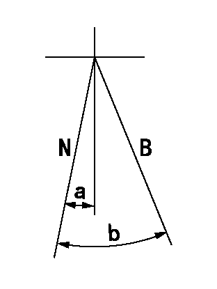
Stop lever angle

N:Pump normal
S:Stop the pump.
----------
----------
a=60deg+-5deg b=73deg+-5deg
----------
----------
a=60deg+-5deg b=73deg+-5deg
0000001101
N:Normal
B:When boosted
----------
----------
a=(5deg) b=(16deg)
----------
----------
a=(5deg) b=(16deg)
0000001501 RACK SENSOR

V1:Supply voltage
V2f:Full side output voltage
V2i:Idle side output voltage
(A) Black
(B) Yellow
(C) Red
(D) Trimmer
(E): Shaft
(F) Nut
(G) Load lever
1. Load sensor adjustment
(1)Connect as shown in the above diagram and apply supply voltage V1.
(2)Hold the load lever (G) against the full side.
(3)Turn the shaft so that the voltage between (A) and (B) is V2.
(4)Hold the load lever (G) against the idle side.
(5)Adjust (D) so that the voltage between (A) and (B) is V2i.
(6)Repeat the above adjustments.
(7)Tighten the nut (F) at the point satisfying the standards.
(8)Hold the load lever against the full side stopper and the idle side stopper.
(9)At this time, confirm that the full side output voltage is V2f and the idle side output voltage is V2i.
----------
V1=5+-0.02V V2f=0.15+0.03V V2i=2.35-0.03V
----------
----------
V1=5+-0.02V V2f=0.15+0.03V V2i=2.35-0.03V
----------
Timing setting

(1)Pump vertical direction
(2)Position of "Z" mark at the No 1 cylinder's beginning of injection (governor side)
(3)B.T.D.C.: aa
(4)-
----------
aa=11deg
----------
a=(170deg)
----------
aa=11deg
----------
a=(170deg)
Information:
Start By:a. remove flywheel
The crankshaft rear seal and wear sleeve must both be removed because they must be replaced as a new set. The new seal set must not be separated.
1. Use a sharp punch and a hammer to put four equally spaced holes in seal (1).2. Install the tip of Tool (A) into the seal, and use the slide hammer to pull it out of the flywheel housing. Change the location of Tool (A) in the seal in order to pull the seal out evenly. 3. Install two 5/8 "-18 NF × 4 in. (102 mm) long bolts (2) to hold the crankshaft rear gear in position.4. Install 5P-7314 Distorter Ring (3) [part of Tooling (B)] in the space where the seal was removed.
Be careful not to damage the crankshaft rear gear.
5. Use 5P-7312 Distorter Ring (4) [part of Tooling (B)] to distort the wear sleeve. Put the end of the distorter in the space where the seal was removed.6. Turn the distorter to cause distortion to the wear sleeve. Move the distorter to another position, and turn the distorter again. Do this procedure until the wear sleeve is loose on the crankshaft.7. Remove the distorter, distorter ring and wear sleeve.Install Crankshaft Rear Seal & Wear Sleeve
The front and rear seals and wear sleeves have different spiral grooves in the seal. Because of this type of design, the front seal group for an engine is different from the rear seal group. If a seal group is installed on the wrong end of the engine, oil can actually be taken out of the engine instead of moving the oil back into the engine.
1. Fasten Tooling (A) to the crankshaft rear gear.2. Use 6V-1541 Quick Cure Primer to clean the outside diameter of the crankshaft rear gear and inside diameter of the wear sleeve in seal assembly (1).3. Put 9S-3265 Retaining Compound on the outside diameter of the crankshaft rear gear and the inside diameter of the wear sleeve in seal assembly (1).
Do not separate the lip-type seal from the wear sleeve. The material in the large lip of the seal can be damaged easily. A scratch or rub (not visible) from a finger can damage the seal enough that it cannot be used. Install the sleeve in the seal. Once there is separation of the sleeve and lip-type seal they cannot be used again and must be replaced with a new seal group. Do not use any type of lubrication during installation of the seal group. If any type of lubrication is used in the installation of the seal group, early seal failure can result.
4. Put seal group (1) in position on Tooling (A). Be sure direction arrows on the seal are the same as crankshaft rotation. 5. Put clean engine oil on the face of washer on nut (2) [part of Tooling (B)] that contacts the installer.6. Install Tooling (B) onto Tooling (A), and install nut (2) [part of Tooling (B)] on the threaded shaft of Tooling