Information injection-pump assembly
ZEXEL
106871-1015
1068711015
Rating:
Cross reference number
ZEXEL
106871-1015
1068711015
Zexel num
Bosch num
Firm num
Name
Calibration Data:
Adjustment conditions
Test oil
1404 Test oil ISO4113 or {SAEJ967d}
1404 Test oil ISO4113 or {SAEJ967d}
Test oil temperature
degC
40
40
45
Nozzle and nozzle holder
105780-8140
Bosch type code
EF8511/9A
Nozzle
105780-0000
Bosch type code
DN12SD12T
Nozzle holder
105780-2080
Bosch type code
EF8511/9
Opening pressure
MPa
17.2
Opening pressure
kgf/cm2
175
Injection pipe
Outer diameter - inner diameter - length (mm) mm 8-3-600
Outer diameter - inner diameter - length (mm) mm 8-3-600
Overflow valve opening pressure
kPa
157
123
191
Overflow valve opening pressure
kgf/cm2
1.6
1.25
1.95
Tester oil delivery pressure
kPa
157
157
157
Tester oil delivery pressure
kgf/cm2
1.6
1.6
1.6
Direction of rotation (viewed from drive side)
Right R
Right R
Injection timing adjustment
Direction of rotation (viewed from drive side)
Right R
Right R
Injection order
1-8-7-3-
6-5-4-2
Pre-stroke
mm
4.2
4.17
4.23
Beginning of injection position
Governor side NO.1
Governor side NO.1
Difference between angles 1
Cal 1-8 deg. 45 44.75 45.25
Cal 1-8 deg. 45 44.75 45.25
Difference between angles 2
Cal 1-7 deg. 90 89.75 90.25
Cal 1-7 deg. 90 89.75 90.25
Difference between angles 3
Cal 1-3 deg. 135 134.75 135.25
Cal 1-3 deg. 135 134.75 135.25
Difference between angles 4
Cal 1-6 deg. 180 179.75 180.25
Cal 1-6 deg. 180 179.75 180.25
Difference between angles 5
Cal 1-5 deg. 225 224.75 225.25
Cal 1-5 deg. 225 224.75 225.25
Difference between angles 6
Cal 1-4 deg. 270 269.75 270.25
Cal 1-4 deg. 270 269.75 270.25
Difference between angles 7
Cyl.1-2 deg. 315 314.75 315.25
Cyl.1-2 deg. 315 314.75 315.25
Injection quantity adjustment
Adjusting point
A
Rack position
8.2
Pump speed
r/min
1200
1200
1200
Average injection quantity
mm3/st.
99.8
97.8
101.8
Max. variation between cylinders
%
0
-3
3
Fixing the lever
*
Boost pressure
kPa
30.7
30.7
Boost pressure
mmHg
230
230
Injection quantity adjustment_02
Adjusting point
B
Rack position
8.7
Pump speed
r/min
650
650
650
Average injection quantity
mm3/st.
109.2
107.7
110.7
Max. variation between cylinders
%
0
-2
2
Basic
*
Fixing the lever
*
Boost pressure
kPa
30.7
30.7
Boost pressure
mmHg
230
230
Injection quantity adjustment_03
Adjusting point
C
Rack position
5.5+-0.5
Pump speed
r/min
225
225
225
Average injection quantity
mm3/st.
8.8
7.4
10.2
Max. variation between cylinders
%
0
-13
13
Fixing the rack
*
Boost pressure
kPa
0
0
0
Boost pressure
mmHg
0
0
0
Injection quantity adjustment_04
Adjusting point
D
Rack position
-
Pump speed
r/min
150
150
150
Average injection quantity
mm3/st.
90
90
Fixing the lever
*
Boost pressure
kPa
0
0
0
Boost pressure
mmHg
0
0
0
Injection quantity adjustment_05
Adjusting point
E
Rack position
11.8+-0.
5
Pump speed
r/min
150
150
150
Average injection quantity
mm3/st.
141
141
151
Fixing the lever
*
Boost pressure
kPa
0
0
0
Boost pressure
mmHg
0
0
0
Remarks
Set the excess lever.
Set the excess lever.
Boost compensator adjustment
Pump speed
r/min
600
600
600
Rack position
7.7
Boost pressure
kPa
6.7
5.4
8
Boost pressure
mmHg
50
40
60
Boost compensator adjustment_02
Pump speed
r/min
600
600
600
Rack position
8.7
Boost pressure
kPa
17.3
17.3
17.3
Boost pressure
mmHg
130
130
130
Test data Ex:
Governor adjustment
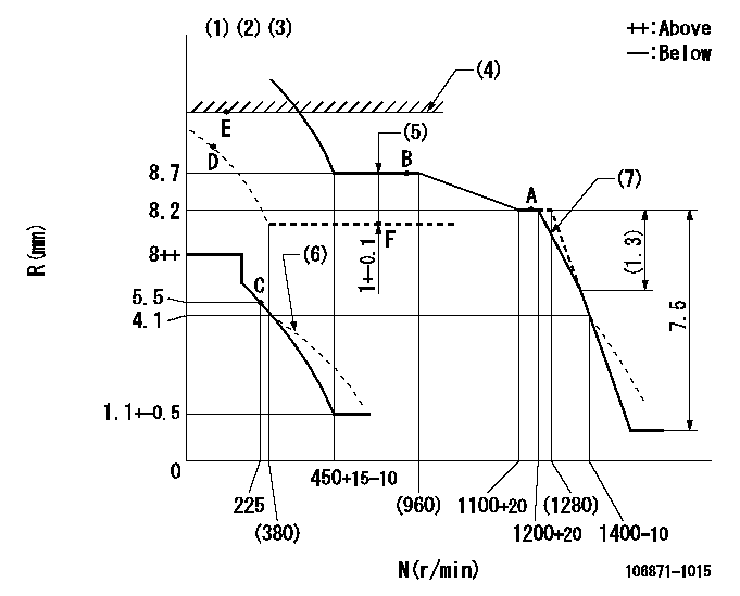
N:Pump speed
R:Rack position (mm)
(1)Lever ratio: RT
(2)Target shim dimension: TH
(3)Supply solenoid operating voltage DC24V and move the solenoid body so that the excess lever reaches the excess position at the solenoid's maximum stroke.
(4)Excess fuel lever setting
(5)Boost compensator stroke
(6)Beginning of damper spring operation: DL
(7)Set the torque spring.
----------
RT=0.8 TH=1.7mm DL=4.1-0.5mm
----------
----------
RT=0.8 TH=1.7mm DL=4.1-0.5mm
----------
Timer adjustment

(1)Adjusting range
(2)Step response time
(N): Speed of the pump
(L): Load
(theta) Advance angle
(Srd1) Step response time 1
(Srd2) Step response time 2
1. Adjusting conditions for the variable timer
(1)Adjust the clearance between the pickup and the protrusion to L.
----------
L=1-0.2mm N2=800r/min C2=(5.375)deg t1=1.5--sec. t2=1.5--sec.
----------
N1=950++r/min P1=0kPa(0kgf/cm2) P2=392kPa(4kgf/cm2) C1=5.375+-0.3deg R01=0/4load R02=4/4load
----------
L=1-0.2mm N2=800r/min C2=(5.375)deg t1=1.5--sec. t2=1.5--sec.
----------
N1=950++r/min P1=0kPa(0kgf/cm2) P2=392kPa(4kgf/cm2) C1=5.375+-0.3deg R01=0/4load R02=4/4load
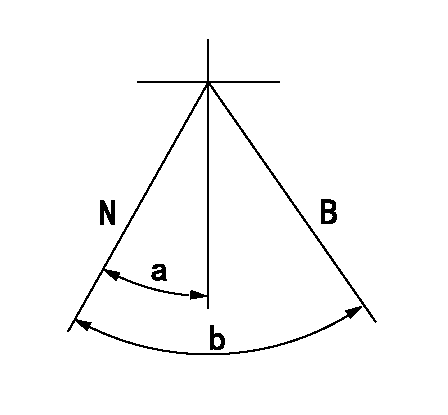
Speed control lever angle

F:Full speed
----------
----------
a=10deg+-5deg
----------
----------
a=10deg+-5deg
0000000901

F:Full load
I:Idle
(1)Stopper bolt setting
----------
----------
a=15deg+-5deg b=42deg+-3deg
----------
----------
a=15deg+-5deg b=42deg+-3deg
Stop lever angle

N:Pump normal
S:Stop the pump.
----------
----------
a=60deg+-5deg b=73deg+-5deg
----------
----------
a=60deg+-5deg b=73deg+-5deg
0000001101
N:Normal
B:When boosted
----------
----------
a=(5deg) b=(16deg)
----------
----------
a=(5deg) b=(16deg)
Timing setting

(1)Pump vertical direction
(2)Position of "Z" mark at the No 1 cylinder's beginning of injection (governor side)
(3)B.T.D.C.: aa
(4)-
----------
aa=11deg
----------
a=(170deg)
----------
aa=11deg
----------
a=(170deg)
Information:
Start By:a. remove oil pump 1. Check each main bearing cap (2) for its location on the engine. Each cap has an arrow (1) to show the front of the block and a number (3) which gives the location of that cap.2. Remove No. 2 through No. 4 main bearing caps from the engine. Remove the lower bearings from the caps.3. Remove the thrust plate from each side of the No. 3 upper main bearing.
If the crankshaft is turned in the wrong direction, the tab of the bearing will be pushed between the crankshaft and the cylinder block. This will cause damage to the crankshaft and block.
4. Turn the crankshaft until Tool (A) can be installed in oil hole (4). Turn the crankshaft in the direction which will push the upper main bearing out, tab end first. Install the main bearings dry when clearance checks are made. Put clean engine oil on the main bearings for final assembly.5. Install the lower bearings in the bearing caps.6. Install the upper bearing in the cylinder block with Tool (A). Be sure tab (5) on the back of the bearings fits in the groove of the caps and cylinder block.The serviceman must be very careful to use Plastigage correctly. The following points must be remembered:... Make sure that the backs of the bearings and the bores are clean and dry. ... Make sure that the bearing locking tabs are properly seated in their slots.... The crankshaft must be free of oil where the Plastigage touches it.... Put a piece of Plastigage on the crown of the bearing half that is in the cap. Do not allow the Plastigage to extend over the edge of the bearing.... Install the bearing cap using the correct torque-turn specifications. Do not use an impact wrench. Be careful not to dislodge the bearing when the cap is installed.... Do not turn the crankshaft with the Plastigage installed.... Carefully remove the cap but do not remove the Plastigage. Measure the width of the Plastigage while it is in the bearing cap or on the crankshaft journal. Do this by using the correct scale on the package. Record the measurements.... Remove the Plastigage before reinstalling the cap.When using Plastigage, the readings can sometimes be unclear. For example, all parts of the Plastigage are not the same width. Measure the major widths to make sure that they are within the specification range. Also, experience has shown that when checking clearances tighter than 0.10 mm (.004 in) the readings may be low by 0.013 to 0.025 mm (.0005 to .0010 in). Out-of-round journals can give faulty readings. Also, journal taper may be indicated when one end of the Plastigage is wider that the other.For complete details concerning measuring bearing clearances, see Engine Bearings & Crankshafts, SEBD0531.7. Check the bearing clearance with Tool (B) as follows:
When Plastigage is used to check bearing clearance, do not use an impact wrench for the torque tightening sequence. However, an impact wrench can be used