Information injection-pump assembly
ZEXEL
106871-1013
1068711013
ISUZU
1156014583
1156014583
Rating:
Service parts 106871-1013 INJECTION-PUMP ASSEMBLY:
1.
_
2.
FUEL INJECTION PUMP
3.
GOVERNOR
6.
COUPLING PLATE
7.
COUPLING PLATE
8.
_
9.
_
11.
Nozzle and Holder
1-15300-141-1
12.
Open Pre:MPa(Kqf/cm2)
15.7{160}/22.1{225}
15.
NOZZLE SET
Include in #1:
106871-1013
as INJECTION-PUMP ASSEMBLY
Cross reference number
ZEXEL
106871-1013
1068711013
ISUZU
1156014583
1156014583
Zexel num
Bosch num
Firm num
Name
Calibration Data:
Adjustment conditions
Test oil
1404 Test oil ISO4113 or {SAEJ967d}
1404 Test oil ISO4113 or {SAEJ967d}
Test oil temperature
degC
40
40
45
Nozzle and nozzle holder
105780-8140
Bosch type code
EF8511/9A
Nozzle
105780-0000
Bosch type code
DN12SD12T
Nozzle holder
105780-2080
Bosch type code
EF8511/9
Opening pressure
MPa
17.2
Opening pressure
kgf/cm2
175
Injection pipe
Outer diameter - inner diameter - length (mm) mm 8-3-600
Outer diameter - inner diameter - length (mm) mm 8-3-600
Overflow valve
132424-0620
Overflow valve opening pressure
kPa
157
123
191
Overflow valve opening pressure
kgf/cm2
1.6
1.25
1.95
Tester oil delivery pressure
kPa
157
157
157
Tester oil delivery pressure
kgf/cm2
1.6
1.6
1.6
Direction of rotation (viewed from drive side)
Right R
Right R
Injection timing adjustment
Direction of rotation (viewed from drive side)
Right R
Right R
Injection order
1-8-7-3-
6-5-4-2
Pre-stroke
mm
4.2
4.17
4.23
Beginning of injection position
Governor side NO.1
Governor side NO.1
Difference between angles 1
Cal 1-8 deg. 45 44.75 45.25
Cal 1-8 deg. 45 44.75 45.25
Difference between angles 2
Cal 1-7 deg. 90 89.75 90.25
Cal 1-7 deg. 90 89.75 90.25
Difference between angles 3
Cal 1-3 deg. 135 134.75 135.25
Cal 1-3 deg. 135 134.75 135.25
Difference between angles 4
Cal 1-6 deg. 180 179.75 180.25
Cal 1-6 deg. 180 179.75 180.25
Difference between angles 5
Cal 1-5 deg. 225 224.75 225.25
Cal 1-5 deg. 225 224.75 225.25
Difference between angles 6
Cal 1-4 deg. 270 269.75 270.25
Cal 1-4 deg. 270 269.75 270.25
Difference between angles 7
Cyl.1-2 deg. 315 314.75 315.25
Cyl.1-2 deg. 315 314.75 315.25
Injection quantity adjustment
Adjusting point
A
Rack position
8.5
Pump speed
r/min
1200
1200
1200
Average injection quantity
mm3/st.
102.8
100.8
104.8
Max. variation between cylinders
%
0
-3
3
Fixing the lever
*
Boost pressure
kPa
22.7
22.7
Boost pressure
mmHg
170
170
Injection quantity adjustment_02
Adjusting point
B
Rack position
9
Pump speed
r/min
700
700
700
Average injection quantity
mm3/st.
103.4
101.9
104.9
Max. variation between cylinders
%
0
-2
2
Basic
*
Fixing the lever
*
Boost pressure
kPa
22.7
22.7
Boost pressure
mmHg
170
170
Injection quantity adjustment_03
Adjusting point
C
Rack position
6.2+-0.5
Pump speed
r/min
225
225
225
Average injection quantity
mm3/st.
14.5
13.1
15.9
Max. variation between cylinders
%
0
-13
13
Fixing the rack
*
Boost pressure
kPa
0
0
0
Boost pressure
mmHg
0
0
0
Remarks
Adjust only variation between cylinders; adjust governor according to governor specifications.
Adjust only variation between cylinders; adjust governor according to governor specifications.
Injection quantity adjustment_04
Adjusting point
E
Rack position
12+-0.5
Pump speed
r/min
150
150
150
Average injection quantity
mm3/st.
134.3
134.3
144.3
Fixing the lever
*
Boost pressure
kPa
0
0
0
Boost pressure
mmHg
0
0
0
Remarks
Set the excess lever.
Set the excess lever.
Boost compensator adjustment
Pump speed
r/min
500
500
500
Rack position
8.7
Boost pressure
kPa
6.7
5.4
8
Boost pressure
mmHg
50
40
60
Boost compensator adjustment_02
Pump speed
r/min
500
500
500
Rack position
9
Boost pressure
kPa
9.3
9.3
9.3
Boost pressure
mmHg
70
70
70
Test data Ex:
Governor adjustment
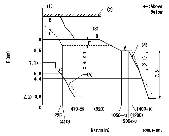
N:Pump speed
R:Rack position (mm)
(1)Supply solenoid operating voltage DC24V and move the solenoid body so that the excess lever reaches the excess position at the solenoid's maximum stroke.
(2)Excess fuel lever setting
(3)Boost compensator stroke
(4)Set the torque spring.
(5)Beginning of damper spring operation: DL
----------
DL=4.4-0.5mm
----------
----------
DL=4.4-0.5mm
----------
Timer adjustment

(1)Adjusting range
(2)Step response time
(N): Speed of the pump
(L): Load
(theta) Advance angle
(Srd1) Step response time 1
(Srd2) Step response time 2
1. Adjusting conditions for the variable timer
(1)Adjust the clearance between the pickup and the protrusion to L.
----------
L=1-0.2mm N2=800r/min C2=(5.375)deg t1=1.5--sec. t2=1.5--sec.
----------
N1=950++r/min P1=0kPa(0kgf/cm2) P2=392kPa(4kgf/cm2) C1=5.375+-0.3deg R01=0/4load R02=4/4load
----------
L=1-0.2mm N2=800r/min C2=(5.375)deg t1=1.5--sec. t2=1.5--sec.
----------
N1=950++r/min P1=0kPa(0kgf/cm2) P2=392kPa(4kgf/cm2) C1=5.375+-0.3deg R01=0/4load R02=4/4load
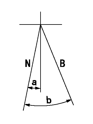
Speed control lever angle

F:Full speed
----------
----------
a=10deg+-5deg
----------
----------
a=10deg+-5deg
0000000901

F:Full load
I:Idle
(1)Stopper bolt setting
----------
----------
a=10deg+-5deg b=36deg+-3deg
----------
----------
a=10deg+-5deg b=36deg+-3deg
Stop lever angle

N:Pump normal
S:Stop the pump.
----------
----------
a=60deg+-5deg b=73deg+-5deg
----------
----------
a=60deg+-5deg b=73deg+-5deg
0000001101
N:Normal
B:When boosted
----------
----------
a=(5deg) b=(16deg)
----------
----------
a=(5deg) b=(16deg)
0000001501 RACK SENSOR

V1:Supply voltage
V2f:Full side output voltage
V2i:Idle side output voltage
(A) Black
(B) Yellow
(C) Red
(D) Trimmer
(E): Shaft
(F) Nut
(G) Load lever
1. Load sensor adjustment
(1)Connect as shown in the above diagram and apply supply voltage V1.
(2)Hold the load lever (G) against the full side.
(3)Turn the shaft so that the voltage between (A) and (B) is V2.
(4)Hold the load lever (G) against the idle side.
(5)Adjust (D) so that the voltage between (A) and (B) is V2i.
(6)Repeat the above adjustments.
(7)Tighten the nut (F) at the point satisfying the standards.
(8)Hold the load lever against the full side stopper and the idle side stopper.
(9)At this time, confirm that the full side output voltage is V2f and the idle side output voltage is V2i.
----------
V1=5+-0.02V V2f=0.15+0.03V V2i=2.35-0.03V
----------
----------
V1=5+-0.02V V2f=0.15+0.03V V2i=2.35-0.03V
----------
Timing setting

(1)Pump vertical direction
(2)Position of "Z" mark at the No 1 cylinder's beginning of injection (governor side)
(3)B.T.D.C.: aa
(4)-
----------
aa=11deg
----------
a=(170deg)
----------
aa=11deg
----------
a=(170deg)
Information:
Do not turn the crankshaft while any of the connecting rods are in the engine without the caps installed.
1. Remove the carbon from the top inside surface of the cylinder liners.2. Turn the crankshaft until two pistons are at bottom center.3. Remove bearing caps (1) from the two connecting rods. 4. Push the pistons up until the piston rings are clear of the cylinder liner. Remove pistons (2). Keep each cap with its connecting rod.5. Do Steps 1 through 4 for the remainder of the pistons.Install Pistons & Connecting Rods
1. Put clean engine oil on the piston rings, connecting rod bearings and cylinder liners. 2. Put two pistons in position opposite of each other in the correct bore of the block. Install pistons (1) with Tool (A).
Make sure that the pistons are installed with flat surfaces (2) of the connecting rods toward each other and the chamfered sides (4) toward the crankshaft.
For more detail about the installation of connecting rod bearings, see Remove & Install Connecting Rod Bearings.
Do not use an impact wrench to tighten the nuts the additional 120 degrees when the bearing clearance is checked.
3. Check the bearing clearances with Plastigage.4. Put 2P-2506 Thread Lubricant on bolts (5). Install caps (3) and the nuts finger tight. Tighten each nut to a torque of 81 8 N m (60 6 lb ft). Put a mark across the nuts and bolts. Tighten each nut 120 degrees more.5. Check the side clearance between two connecting rods on the same crankshaft journal. The clearance must be 0.28 to 0.84 mm (.011 to .033 in) for new rods.6. Do Steps 1 through 5 for the remainder of the pistons.End By:a. install piston cooling tubesb. install oil pumpc. install cylinder headsDisassemble & Assemble Pistons & Connecting Rods
Start By:a. remove pistons and connecting rods 1. Remove bearings (3) from the connecting rod and connecting rod cap. The new style retainer rings allow the use of pliers to remove retainer ring (1).2. Remove retainer ring (1) with Tool (A) or pliers.3. Remove pin (2) and connecting rod (4) from the pistons. 4. Remove piston rings (5) from the piston with Tool (B). Clean the piston ring grooves on the pistons with an acceptable ring groove cleaning tool. See Use Of Piston Pin Bearing Removal & Installation Tools, Special Instructions, SMHS7295-02.5. Heat connecting rod (4) in an oven to a temperature of 177° to 260° C (350° to 500° F). Never use a direct flame to heat a connecting rod. 6. Put connecting rod (4) in position on the base plate of Tooling (C). Put a new rod pin bearing (6) on the adapter part of Tooling (C). The old bearing is pushed out by Tooling (C) as the new bearing is installed.7. Use Tooling (C) to push the new bearing into the connecting rod until the push adapter of Tooling (C) makes full contact with the connecting rod surface.8. Use a pin boring machine to make the rod pin bearing the