Information injection-pump assembly
ZEXEL
106871-1010
1068711010
ISUZU
1156027370
1156027370
Rating:
Service parts 106871-1010 INJECTION-PUMP ASSEMBLY:
1.
_
6.
COUPLING PLATE
7.
COUPLING PLATE
8.
_
9.
_
11.
Nozzle and Holder
1-15300-141-1
12.
Open Pre:MPa(Kqf/cm2)
15.7(160)/22.1(225)
15.
NOZZLE SET
Include in #1:
106871-1010
as INJECTION-PUMP ASSEMBLY
Cross reference number
ZEXEL
106871-1010
1068711010
ISUZU
1156027370
1156027370
Zexel num
Bosch num
Firm num
Name
Calibration Data:
Adjustment conditions
Test oil
1404 Test oil ISO4113 or {SAEJ967d}
1404 Test oil ISO4113 or {SAEJ967d}
Test oil temperature
degC
40
40
45
Nozzle and nozzle holder
105780-8140
Bosch type code
EF8511/9A
Nozzle
105780-0000
Bosch type code
DN12SD12T
Nozzle holder
105780-2080
Bosch type code
EF8511/9
Opening pressure
MPa
17.2
Opening pressure
kgf/cm2
175
Injection pipe
Outer diameter - inner diameter - length (mm) mm 8-3-600
Outer diameter - inner diameter - length (mm) mm 8-3-600
Overflow valve opening pressure
kPa
157
123
191
Overflow valve opening pressure
kgf/cm2
1.6
1.25
1.95
Tester oil delivery pressure
kPa
157
157
157
Tester oil delivery pressure
kgf/cm2
1.6
1.6
1.6
Direction of rotation (viewed from drive side)
Right R
Right R
Injection timing adjustment
Direction of rotation (viewed from drive side)
Right R
Right R
Injection order
1-8-7-3-
6-5-4-2
Pre-stroke
mm
4.2
4.17
4.23
Beginning of injection position
Governor side NO.1
Governor side NO.1
Difference between angles 1
Cal 1-8 deg. 45 44.75 45.25
Cal 1-8 deg. 45 44.75 45.25
Difference between angles 2
Cal 1-7 deg. 90 89.75 90.25
Cal 1-7 deg. 90 89.75 90.25
Difference between angles 3
Cal 1-3 deg. 135 134.75 135.25
Cal 1-3 deg. 135 134.75 135.25
Difference between angles 4
Cal 1-6 deg. 180 179.75 180.25
Cal 1-6 deg. 180 179.75 180.25
Difference between angles 5
Cal 1-5 deg. 225 224.75 225.25
Cal 1-5 deg. 225 224.75 225.25
Difference between angles 6
Cal 1-4 deg. 270 269.75 270.25
Cal 1-4 deg. 270 269.75 270.25
Difference between angles 7
Cyl.1-2 deg. 315 314.75 315.25
Cyl.1-2 deg. 315 314.75 315.25
Injection quantity adjustment
Adjusting point
A
Rack position
8.2
Pump speed
r/min
1200
1200
1200
Average injection quantity
mm3/st.
99.8
97.8
101.8
Max. variation between cylinders
%
0
-3
3
Fixing the lever
*
Boost pressure
kPa
30.7
30.7
Boost pressure
mmHg
230
230
Injection quantity adjustment_02
Adjusting point
B
Rack position
8.7
Pump speed
r/min
650
650
650
Average injection quantity
mm3/st.
109.2
107.7
110.7
Max. variation between cylinders
%
0
-2
2
Basic
*
Fixing the lever
*
Boost pressure
kPa
30.7
30.7
Boost pressure
mmHg
230
230
Injection quantity adjustment_03
Adjusting point
C
Rack position
5.5+-0.5
Pump speed
r/min
225
225
225
Average injection quantity
mm3/st.
8.8
7.4
10.2
Max. variation between cylinders
%
0
-13
13
Fixing the rack
*
Boost pressure
kPa
0
0
0
Boost pressure
mmHg
0
0
0
Injection quantity adjustment_04
Adjusting point
D
Rack position
-
Pump speed
r/min
150
150
150
Average injection quantity
mm3/st.
90
90
Fixing the lever
*
Boost pressure
kPa
0
0
0
Boost pressure
mmHg
0
0
0
Injection quantity adjustment_05
Adjusting point
E
Rack position
11.8+-0.
5
Pump speed
r/min
150
150
150
Average injection quantity
mm3/st.
141
141
151
Fixing the lever
*
Boost pressure
kPa
0
0
0
Boost pressure
mmHg
0
0
0
Remarks
Startup boost setting
Startup boost setting
Boost compensator adjustment
Pump speed
r/min
600
600
600
Rack position
7.7
Boost pressure
kPa
6.7
5.4
8
Boost pressure
mmHg
50
40
60
Boost compensator adjustment_02
Pump speed
r/min
600
600
600
Rack position
8.7
Boost pressure
kPa
17.3
17.3
17.3
Boost pressure
mmHg
130
130
130
Test data Ex:
Governor adjustment
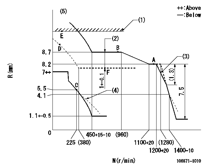
N:Pump speed
R:Rack position (mm)
(1)Excess fuel lever setting
(2)Boost compensator stroke
(3)Set the torque spring.
(4)Beginning of damper spring operation: DL
(5)Supply solenoid operating voltage DC24V and move the solenoid body so that the excess lever reaches the excess position at the solenoid's maximum stroke.
----------
DL=4.1-0.5mm
----------
----------
DL=4.1-0.5mm
----------
Timer adjustment

(1)Adjusting range
(2)Step response time
(N): Speed of the pump
(L): Load
(theta) Advance angle
(Srd1) Step response time 1
(Srd2) Step response time 2
1. Adjusting conditions for the variable timer
(1)Adjust the clearance between the pickup and the protrusion to L.
----------
L=1-0.2mm N2=800r/min C2=(5.375)deg t1=1.5--sec. t2=1.5--sec.
----------
N1=950++r/min P1=0kPa(0kgf/cm2) P2=392kPa(4kgf/cm2) C1=5.375+-0.3deg R01=0/4load R02=4/4load
----------
L=1-0.2mm N2=800r/min C2=(5.375)deg t1=1.5--sec. t2=1.5--sec.
----------
N1=950++r/min P1=0kPa(0kgf/cm2) P2=392kPa(4kgf/cm2) C1=5.375+-0.3deg R01=0/4load R02=4/4load
Speed control lever angle

F:Full speed
----------
----------
a=10deg+-5deg
----------
----------
a=10deg+-5deg
0000000901

F:Full load
I:Idle
(1)Stopper bolt setting
----------
----------
a=15deg+-5deg b=42deg+-3deg
----------
----------
a=15deg+-5deg b=42deg+-3deg
Stop lever angle

N:Pump normal
S:Stop the pump.
----------
----------
a=60deg+-5deg b=73deg+-5deg
----------
----------
a=60deg+-5deg b=73deg+-5deg
0000001101
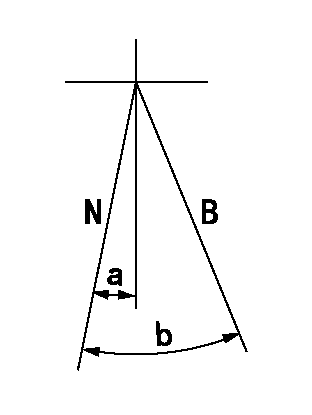
N:Normal
B:When boosted
----------
----------
a=(5deg) b=(16deg)
----------
----------
a=(5deg) b=(16deg)
0000001501 RACK SENSOR

V1:Supply voltage
V2f:Full side output voltage
V2i:Idle side output voltage
(A) Black
(B) Yellow
(C) Red
(D) Trimmer
(E): Shaft
(F) Nut
(G) Load lever
1. Load sensor adjustment
(1)Connect as shown in the above diagram and apply supply voltage V1.
(2)Hold the load lever (G) against the full side.
(3)Turn the shaft so that the voltage between (A) and (B) is V2.
(4)Hold the load lever (G) against the idle side.
(5)Adjust (D) so that the voltage between (A) and (B) is V2i.
(6)Repeat the above adjustments.
(7)Tighten the nut (F) at the point satisfying the standards.
(8)Hold the load lever against the full side stopper and the idle side stopper.
(9)At this time, confirm that the full side output voltage is V2f and the idle side output voltage is V2i.
----------
V1=5+-0.02V V2f=0.15+0.03V V2i=2.35-0.03V
----------
----------
V1=5+-0.02V V2f=0.15+0.03V V2i=2.35-0.03V
----------
Timing setting

(1)Pump vertical direction
(2)Position of "Z" mark at the No 1 cylinder's beginning of injection (governor side)
(3)B.T.D.C.: aa
(4)-
----------
aa=11deg
----------
a=(170deg)
----------
aa=11deg
----------
a=(170deg)
Information:
Start By:a. remove valve covers1. Turn the flywheel with Tool (C) until there is clearance between the rocker arms and valve bridges. 2. Engage Tool (A) with the rocker arm, and move Tool (A) against the valve spring force until push rod (1) can be removed.3. Remove the other push rod for the same cylinder. Mark each push rod so it can be installed in its original position. 4. Use Tool (B) to remove valve lifter (2).5. Remove the other valve lifter for the same cylinder. Mark each valve lifter so it can be installed in its original position. 6. Remove spring (3) from lifter (2).7. Inspect spring (3). See Guideline For Reusable Parts, SEBF8066. 8. Identify the location of each valve bridge (4), then remove them.Install Push Rods, Valve Lifters & Valve Bridges
1. Put clean engine oil on each bridge dowel and the bore of each bridge. Install bridges (1) in their original position.2. Use the following procedure to adjust the valve bridges.a. Put clean SAE 30 Engine Oil in the lubrication passage of the bridge.b. Press straight down on the top contact surface of the bridge with a force of 4.45 to 44.50 N (1 to 10 lb).c. Turn the adjusting screw clockwise until the oil film in the lubrication passage of the bridge moves inward.d. Turn the adjusting screw an additional 20 to 30 degrees (1/3 to 1/2 of a flat on the hex nut).e. Hold the adjusting screw in position, and tighten the locknut to a torque of 26 to 34 N m (19 to 25 lb ft).f. Do this procedure for both bridges. Put clean engine oil on the top contact surface of both bridges. 3. Install spring (3) on valve lifter (2). 4. Fasten Tool (A) to valve lifter (2).5. Immerse valve lifter (2) in clean engine oil; then install it in its original position.6. Install the other valve lifter for the same cylinder. 7. Engage Tool (B) with the rocker arm, and move Tool (B) against the valve spring force until push rods (4) can be installed in their original position.8. Use Tool (C) to turn the flywheel so the remaining push rods can be installed. Be sure there is clearance at the rocker arms and valve bridges before compressing the valve pump.9. Check the valve clearance settings. The clearance for the intake valves is 0.38 mm (.015 in). The clearance for the exhaust valve is 0.76 mm (.030 in). See the topic "Valve Clearance Setting" in Testing & Adjusting.End By:a. install valve covers
1. Put clean engine oil on each bridge dowel and the bore of each bridge. Install bridges (1) in their original position.2. Use the following procedure to adjust the valve bridges.a. Put clean SAE 30 Engine Oil in the lubrication passage of the bridge.b. Press straight down on the top contact surface of the bridge with a force of 4.45 to 44.50 N (1 to 10 lb).c. Turn the adjusting screw clockwise until the oil film in the lubrication passage of the bridge moves inward.d. Turn the adjusting screw an additional 20 to 30 degrees (1/3 to 1/2 of a flat on the hex nut).e. Hold the adjusting screw in position, and tighten the locknut to a torque of 26 to 34 N m (19 to 25 lb ft).f. Do this procedure for both bridges. Put clean engine oil on the top contact surface of both bridges. 3. Install spring (3) on valve lifter (2). 4. Fasten Tool (A) to valve lifter (2).5. Immerse valve lifter (2) in clean engine oil; then install it in its original position.6. Install the other valve lifter for the same cylinder. 7. Engage Tool (B) with the rocker arm, and move Tool (B) against the valve spring force until push rods (4) can be installed in their original position.8. Use Tool (C) to turn the flywheel so the remaining push rods can be installed. Be sure there is clearance at the rocker arms and valve bridges before compressing the valve pump.9. Check the valve clearance settings. The clearance for the intake valves is 0.38 mm (.015 in). The clearance for the exhaust valve is 0.76 mm (.030 in). See the topic "Valve Clearance Setting" in Testing & Adjusting.End By:a. install valve covers