Information injection-pump assembly
ZEXEL
106871-0930
1068710930
Rating:
Service parts 106871-0930 INJECTION-PUMP ASSEMBLY:
1.
_
7.
COUPLING PLATE
8.
_
9.
_
11.
Nozzle and Holder
16600-97068
12.
Open Pre:MPa(Kqf/cm2)
21.6{220}

15.
NOZZLE SET
Include in #1:
106871-0930
as INJECTION-PUMP ASSEMBLY
Cross reference number
ZEXEL
106871-0930
1068710930
Zexel num
Bosch num
Firm num
Name
106871-0930
INJECTION-PUMP ASSEMBLY
Calibration Data:
Adjustment conditions
Test oil
1404 Test oil ISO4113 or {SAEJ967d}
1404 Test oil ISO4113 or {SAEJ967d}
Test oil temperature
degC
40
40
45
Nozzle and nozzle holder
105780-8140
Bosch type code
EF8511/9A
Nozzle
105780-0000
Bosch type code
DN12SD12T
Nozzle holder
105780-2080
Bosch type code
EF8511/9
Opening pressure
MPa
17.2
Opening pressure
kgf/cm2
175
Injection pipe
Outer diameter - inner diameter - length (mm) mm 8-3-600
Outer diameter - inner diameter - length (mm) mm 8-3-600
Overflow valve opening pressure
kPa
157
123
191
Overflow valve opening pressure
kgf/cm2
1.6
1.25
1.95
Tester oil delivery pressure
kPa
157
157
157
Tester oil delivery pressure
kgf/cm2
1.6
1.6
1.6
Direction of rotation (viewed from drive side)
Right R
Right R
Injection timing adjustment
Direction of rotation (viewed from drive side)
Right R
Right R
Injection order
1-8-7-5-
4-3-6-2
Pre-stroke
mm
3.65
3.6
3.7
Beginning of injection position
Governor side NO.1
Governor side NO.1
Difference between angles 1
Cal 1-8 deg. 45 44.5 45.5
Cal 1-8 deg. 45 44.5 45.5
Difference between angles 2
Cal 1-7 deg. 90 89.5 90.5
Cal 1-7 deg. 90 89.5 90.5
Difference between angles 3
Cal 1-5 deg. 135 134.5 135.5
Cal 1-5 deg. 135 134.5 135.5
Difference between angles 4
Cal 1-4 deg. 180 179.5 180.5
Cal 1-4 deg. 180 179.5 180.5
Difference between angles 5
Cal 1-3 deg. 225 224.5 225.5
Cal 1-3 deg. 225 224.5 225.5
Difference between angles 6
Cal 1-6 deg. 270 269.5 270.5
Cal 1-6 deg. 270 269.5 270.5
Difference between angles 7
Cyl.1-2 deg. 315 314.5 315.5
Cyl.1-2 deg. 315 314.5 315.5
Injection quantity adjustment
Adjusting point
A
Rack position
10.1
Pump speed
r/min
700
700
700
Average injection quantity
mm3/st.
127.7
126.7
128.7
Max. variation between cylinders
%
0
-4
4
Basic
*
Fixing the lever
*
Injection quantity adjustment_02
Adjusting point
C
Rack position
6.7+-0.5
Pump speed
r/min
260
260
260
Average injection quantity
mm3/st.
11.1
9.1
13.1
Max. variation between cylinders
%
0
-10
10
Fixing the rack
*
Injection quantity adjustment_03
Adjusting point
D
Rack position
-
Pump speed
r/min
100
100
100
Average injection quantity
mm3/st.
187
187
Fixing the lever
*
Remarks
After startup boost setting
After startup boost setting
Timer adjustment
Pump speed
r/min
500--
Advance angle
deg.
0
0
0
Remarks
Start
Start
Timer adjustment_02
Pump speed
r/min
450
Advance angle
deg.
0.5
Timer adjustment_03
Pump speed
r/min
1100
Advance angle
deg.
3.5
3
4
Remarks
Finish
Finish
Test data Ex:
Governor adjustment
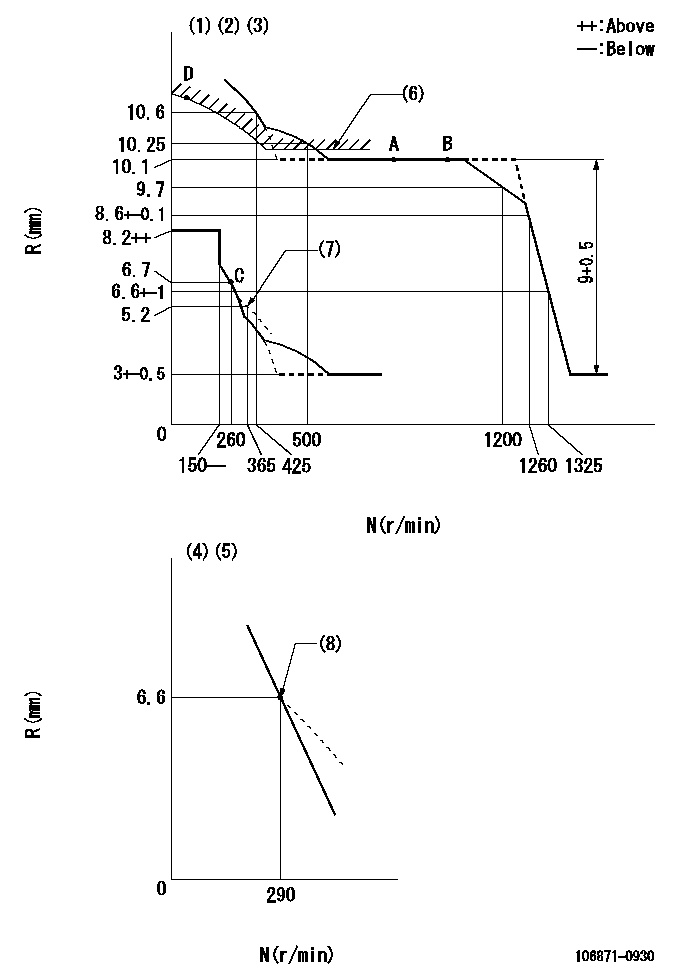
N:Pump speed
R:Rack position (mm)
(1)Lever ratio: RT
(2)Target shim dimension: TH
(3)Tolerance for racks not indicated: +-0.05mm.
(4)Variable speed specification: idling adjustment
(5)Fix the lever at the full-load position at delivery.
(6)Excess fuel setting for starting: SXL
(7)Damper spring setting
(8)Main spring setting
----------
RT=1 TH=1.8mm SXL=10.2+-0.1mm
----------
----------
RT=1 TH=1.8mm SXL=10.2+-0.1mm
----------
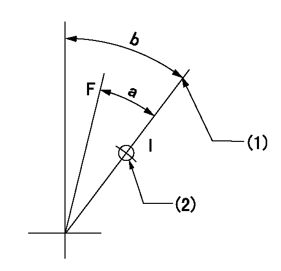
Speed control lever angle

F:Full speed
I:Idle
(1)Pump speed = aa
(2)Set the stopper bolt (fixed at full-load position at delivery.)
----------
aa=290r/min
----------
a=11.5deg+-5deg b=5deg+-5deg
----------
aa=290r/min
----------
a=11.5deg+-5deg b=5deg+-5deg
0000000901
F:Full load
I:Idle
(1)Stopper bolt setting
(2)Use the hole at R = aa
----------
aa=46mm
----------
a=26.5deg+-3deg b=33deg+-5deg
----------
aa=46mm
----------
a=26.5deg+-3deg b=33deg+-5deg
Stop lever angle
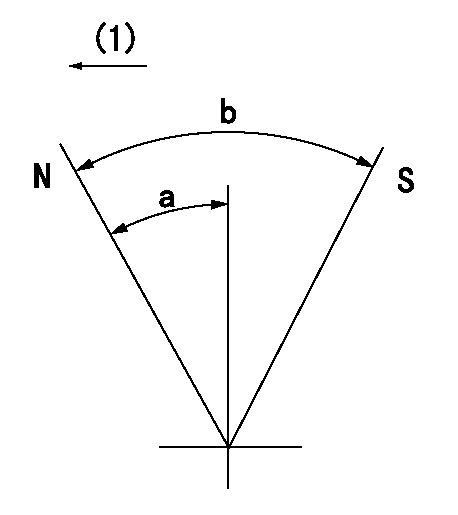
N:Pump normal
S:Stop the pump.
(1)Drive side
----------
----------
a=20deg+-5deg b=64deg+-5deg
----------
----------
a=20deg+-5deg b=64deg+-5deg
Timing setting

(1)Pump vertical direction
(2)Position of the coupling's key groove at the beginning of injection of the No. 8 cylinder.
(3)-
(4)-
----------
----------
a=(90deg)
----------
----------
a=(90deg)
Information:
Start By:a. remove oil pump1. Check the connecting rods and caps for their identification and location. 2. Turn the crankshaft until the connecting rod caps are in position.3. Remove two bolts (1) and the cap from the connecting rod. Remove the lower half of the bearing from the cap.4. Push the connecting rod away from the crankshaft. Remove the upper half of the bearing from the connecting rod. Install the bearings dry when the clearance checks are made. Put clean engine oil on the bearings for final assembly.5. Install the upper half of the bearing in the connecting rod.6. Pull the connecting rod slowly on to the crankshaft.7. Install the lower half of the bearing in the cap. Be sure the tabs in the back of bearings are in the tab grooves of the connecting rod and cap.The serviceman must be very careful to use Plastigage, Tool (A) correctly. The following points must be remembered:Make sure that the backs of the bearings and the bores are clean and dry.Make sure that the bearing locking tabs are properly seated in their slots.The crankshaft must be free of oil where the Plastigage touches it.Put a piece of Plastigage (A) on the crown of the bearing half that is in the cap. Do not allow the Plastigage to extend over the edge of the bearing.Install the bearing cap using the correct torque-turn specifications. Do not use an impact wrench. Be careful not to dislodge the bearing when the cap is installed.Do not turn the crankshaft with the Plastigage installed.Carefully remove the cap but do not remove the Plastigage. Measure the width of the Plastigage while it is in the bearing cap or on the crankshaft journal. Do this by using the correct scale on the package. Record the measurements.Remove the Plastigage before reinstalling the cap.When using Plastigage, the readings can sometimes be unclear. For example, all parts of the Plastigage are not the same width. Measure the major widths to make sure that they are within the specification range. Also, experience has shown that when checking clearances tighter than 0.10 mm (.004 in) the readings may be low by 0.013 to 0.025 mm (.0005 to .0010 in). Out-of-round journals can give faulty readings. Also, journal taper may be indicated when one end of the Plastigage is wider that the other.For complete details concerning measuring bearing clearance, see the topic, "Engine Bearings & Crankshafts", SEBD0531. 8. Use Plastigage (A) to check the bearing clearance.9. Put Plastigage (A) on the bearing.10. Put 2P2506 Thread Lubricant on the threads of the rod bolts and seat surfaces of the nuts. Be sure the cylinder numbers on the rod cap and rod are the same and are on the same side of connecting rod. Numbers are on the same side of the rod and cap as are the bearing tab slots. If new rods are installed, put the cylinder number on the rod and cap. Do not turn the crankshaft when Plastigage (A) is in position.
Have questions with 106871-0930?
Group cross 106871-0930 ZEXEL
Nissan-Diesel
Nissan-Diesel
Nissan-Diesel
106871-0930
INJECTION-PUMP ASSEMBLY