Information injection-pump assembly
ZEXEL
106871-0870
1068710870

Rating:
Service parts 106871-0870 INJECTION-PUMP ASSEMBLY:
1.
_
7.
COUPLING PLATE
8.
_
9.
_
11.
Nozzle and Holder
16600-97073
12.
Open Pre:MPa(Kqf/cm2)
17.7{180}/21.6{220}

15.
NOZZLE SET
Include in #1:
106871-0870
as INJECTION-PUMP ASSEMBLY
Cross reference number
ZEXEL
106871-0870
1068710870
Zexel num
Bosch num
Firm num
Name
106871-0870
INJECTION-PUMP ASSEMBLY
Calibration Data:
Adjustment conditions
Test oil
1404 Test oil ISO4113 or {SAEJ967d}
1404 Test oil ISO4113 or {SAEJ967d}
Test oil temperature
degC
40
40
45
Nozzle and nozzle holder
105780-8140
Bosch type code
EF8511/9A
Nozzle
105780-0000
Bosch type code
DN12SD12T
Nozzle holder
105780-2080
Bosch type code
EF8511/9
Opening pressure
MPa
17.2
Opening pressure
kgf/cm2
175
Injection pipe
Outer diameter - inner diameter - length (mm) mm 8-3-600
Outer diameter - inner diameter - length (mm) mm 8-3-600
Overflow valve opening pressure
kPa
157
123
191
Overflow valve opening pressure
kgf/cm2
1.6
1.25
1.95
Tester oil delivery pressure
kPa
157
157
157
Tester oil delivery pressure
kgf/cm2
1.6
1.6
1.6
Direction of rotation (viewed from drive side)
Right R
Right R
Injection timing adjustment
Direction of rotation (viewed from drive side)
Right R
Right R
Injection order
1-8-7-5-
4-3-6-2
Pre-stroke
mm
3.65
3.6
3.7
Beginning of injection position
Governor side NO.1
Governor side NO.1
Difference between angles 1
Cal 1-8 deg. 45 44.5 45.5
Cal 1-8 deg. 45 44.5 45.5
Difference between angles 2
Cal 1-7 deg. 90 89.5 90.5
Cal 1-7 deg. 90 89.5 90.5
Difference between angles 3
Cal 1-5 deg. 135 134.5 135.5
Cal 1-5 deg. 135 134.5 135.5
Difference between angles 4
Cal 1-4 deg. 180 179.5 180.5
Cal 1-4 deg. 180 179.5 180.5
Difference between angles 5
Cal 1-3 deg. 225 224.5 225.5
Cal 1-3 deg. 225 224.5 225.5
Difference between angles 6
Cal 1-6 deg. 270 269.5 270.5
Cal 1-6 deg. 270 269.5 270.5
Difference between angles 7
Cyl.1-2 deg. 315 314.5 315.5
Cyl.1-2 deg. 315 314.5 315.5
Injection quantity adjustment
Adjusting point
A
Rack position
9.6
Pump speed
r/min
700
700
700
Average injection quantity
mm3/st.
115.7
114.7
116.7
Max. variation between cylinders
%
0
-4
4
Basic
*
Fixing the lever
*
Injection quantity adjustment_02
Adjusting point
B
Rack position
9.6
Pump speed
r/min
1100
1100
1100
Average injection quantity
mm3/st.
120
116
124
Max. variation between cylinders
%
0
-4
4
Fixing the lever
*
Injection quantity adjustment_03
Adjusting point
C
Rack position
6.7+-0.5
Pump speed
r/min
235
235
235
Average injection quantity
mm3/st.
10.4
8.4
12.4
Max. variation between cylinders
%
0
-10
10
Fixing the rack
*
Timer adjustment
Pump speed
r/min
1000
Advance angle
deg.
1.7
1.2
2.2
Timer adjustment_02
Pump speed
r/min
1100
Advance angle
deg.
5
4.5
5.5
Remarks
Finish
Finish
Test data Ex:
Governor adjustment

N:Pump speed
R:Rack position (mm)
(1)Lever ratio: RT
(2)Target shim dimension: TH
(3)Excess fuel setting for starting: SXL
(4)Damper spring setting
(5)Variable speed specification: idling adjustment
(6)Main spring setting
----------
RT=1 TH=1.9mm SXL=10.3+-0.1mm
----------
----------
RT=1 TH=1.9mm SXL=10.3+-0.1mm
----------
Speed control lever angle

F:Full speed
I:Idle
(1)Stopper bolt setting
----------
----------
a=(3.5deg)+-5deg b=(13.5deg)+-5deg
----------
----------
a=(3.5deg)+-5deg b=(13.5deg)+-5deg
0000000901

F:Full load
(1)Stopper bolt setting
(2)Use the hole at R = aa
----------
aa=64.3mm
----------
a=18.5deg+-5deg b=23.5deg+-3deg
----------
aa=64.3mm
----------
a=18.5deg+-5deg b=23.5deg+-3deg
Stop lever angle
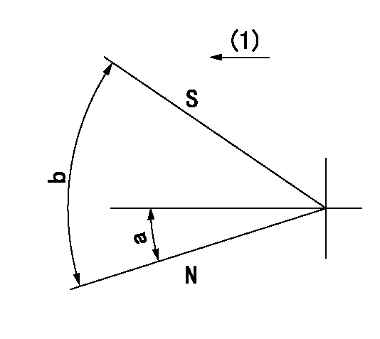
N:Pump normal
S:Stop the pump.
(1)Drive side
----------
----------
a=12deg+-5deg b=64deg+-5deg
----------
----------
a=12deg+-5deg b=64deg+-5deg
Timing setting

(1)Pump vertical direction
(2)Position of the coupling's key groove at the beginning of injection of the No. 8 cylinder.
(3)-
(4)-
----------
----------
a=(90deg)
----------
----------
a=(90deg)
Information:
(1) Fuel pump drive gear (mechanical governor): Diameter of gear bore ... 44.45 to 44.48 mm (1.750 to 1.751 in)Outside diameter of fuel pump hub ... 44.40 to 44.420 mm (1.748 to 1.7488 in)Fuel pump drive gear [hydraulic governor (not shown)]:Diameter of gear bore ... 41.275 to 41.305 mm (1.6250 to 1.6262 in)Outside diameter of gear carrier ... 41.212 to 41.245 mm (1.6225 to 1.6238 in)Running clearance between gear and carrier ... 0.030 to 0.094 mm (0.0012 to 0.0037 in)(2) Camshaft gear: The threads of the removal holes in the camshaft gear have been changed from 5/16 UNF to M8X 1.25. Gears with metric threads have the letter "M" near one of the tapped holes.Diameter of gear bore ... 34.93 to 34.95 mm (1.375 to 1.376 in)Outside diameter of camshaft hub ... 34.902 to 34.917 mm (1.3741 to 1.3747 in)Clearance between gear and camshaft hub ... -0.023 to +0.033 mm (-.0009 to +.0013 in)(3) Torque for camshaft gear bolt ... 70 N m (50 lb ft)(4) Idler gear and hub (with bearing): Inside diameter of gear bearing ... 50.795 to 50.818 mm (1.9998 to 2.0007 in)Outside diameter of gear hub ... 50.700 to 50.737 mm (1.9960 to 1.9975 in)Clearance of gear on hub ... 0.058 to 0.119 mm (0.0023 to 0.0047 in)Idler gear end play ... 0.10 to 0.20 mm (0.004 to 0.008 in)Maximum permissible end play ... 0.25 mm (0.010 in)Idler gear and hub (with needle bearing):Inside diameter of idler gear ... 62.016 to 62.032 mm (2.4414 to 2.4422 in)Outside diameter of bearing ... 69.999 mm (2.4409 in)Clearance between idler gear and bearing ... 0.013 to 0.033 mm (0.0005 to 0.0013 in)Inside diameter of gear bearing ... 55.001 mm (2.1654 in)Outside diameter of gear hub ... 54.988 to 55.001 mm (2.1649 to 2.1654 in)Clearance of gear on hub ... 0.000 to 0.013 mm (0.0000 to 0.0005 in)Idler gear end play ... 0.15 to 0.51 mm (0.006 to 0.020 in)(5) Torque for idler gear bolts ... 40 N m (30 lb ft)(6) Crankshaft gear: Diameter of gear bore ... 47.63 to 47.65 mm (1.875 to 1.876 in)Outside diameter of crankshaft for gear ... 47.630 to 47.638 mm (1.8750 to 1.8755 in)(7) Oil pump idler gear: Diameter of gear bore ... 25.40 to 25.430 mm (1.000 to 1.0012 in)Outside diameter of bearing ... 25.40 to 25.420 mm (1.000 to 1.0008 in)Inside diameter of bearing ... 22.225 to 22.258 mm (0.8750 to 0.8763 in)Outside diameter of idler gear shaft ... 22.192 to 22.205 mm (0.8737 to 0.8742 in)Clearance of gear on shaft ... 0.020 to 0.066 mm (0.0008 to 0.0026 in)Idler gear end play ... 0.05 to 0.41 mm (0.002 to 0.016 in)Timing gear backlash:Minimum ... 0.08 mm (0.003 in)Maximum ... 0.15 mm (0.006 in)
Have questions with 106871-0870?
Group cross 106871-0870 ZEXEL
Nissan-Diesel
Nissan-Diesel
Nissan-Diesel
Nissan-Diesel
Nissan-Diesel
Nissan-Diesel
Nissan-Diesel
Nissan-Diesel
106871-0870
INJECTION-PUMP ASSEMBLY