Information injection-pump assembly
ZEXEL
106871-0732
1068710732
Rating:
Service parts 106871-0732 INJECTION-PUMP ASSEMBLY:
1.
_
7.
COUPLING PLATE
8.
_
9.
_
11.
Nozzle and Holder
16600-97068
12.
Open Pre:MPa(Kqf/cm2)
21.6{220}
15.
NOZZLE SET
Include in #1:
106871-0732
as INJECTION-PUMP ASSEMBLY
Cross reference number
ZEXEL
106871-0732
1068710732
Zexel num
Bosch num
Firm num
Name
106871-0732
INJECTION-PUMP ASSEMBLY
14CD PE8P PE
14CD PE8P PE
Calibration Data:
Adjustment conditions
Test oil
1404 Test oil ISO4113 or {SAEJ967d}
1404 Test oil ISO4113 or {SAEJ967d}
Test oil temperature
degC
40
40
45
Nozzle and nozzle holder
105780-8140
Bosch type code
EF8511/9A
Nozzle
105780-0000
Bosch type code
DN12SD12T
Nozzle holder
105780-2080
Bosch type code
EF8511/9
Opening pressure
MPa
17.2
Opening pressure
kgf/cm2
175
Injection pipe
Outer diameter - inner diameter - length (mm) mm 8-3-600
Outer diameter - inner diameter - length (mm) mm 8-3-600
Overflow valve
132424-0620
Overflow valve opening pressure
kPa
157
123
191
Overflow valve opening pressure
kgf/cm2
1.6
1.25
1.95
Tester oil delivery pressure
kPa
157
157
157
Tester oil delivery pressure
kgf/cm2
1.6
1.6
1.6
Direction of rotation (viewed from drive side)
Right R
Right R
Injection timing adjustment
Direction of rotation (viewed from drive side)
Right R
Right R
Injection order
1-8-7-5-
4-3-6-2
Pre-stroke
mm
3.65
3.6
3.7
Beginning of injection position
Governor side NO.1
Governor side NO.1
Difference between angles 1
Cal 1-8 deg. 45 44.5 45.5
Cal 1-8 deg. 45 44.5 45.5
Difference between angles 2
Cal 1-7 deg. 90 89.5 90.5
Cal 1-7 deg. 90 89.5 90.5
Difference between angles 3
Cal 1-5 deg. 135 134.5 135.5
Cal 1-5 deg. 135 134.5 135.5
Difference between angles 4
Cal 1-4 deg. 180 179.5 180.5
Cal 1-4 deg. 180 179.5 180.5
Difference between angles 5
Cal 1-3 deg. 225 224.5 225.5
Cal 1-3 deg. 225 224.5 225.5
Difference between angles 6
Cal 1-6 deg. 270 269.5 270.5
Cal 1-6 deg. 270 269.5 270.5
Difference between angles 7
Cyl.1-2 deg. 315 314.5 315.5
Cyl.1-2 deg. 315 314.5 315.5
Injection quantity adjustment
Adjusting point
A
Rack position
10.7
Pump speed
r/min
700
700
700
Average injection quantity
mm3/st.
132.2
131.2
133.2
Max. variation between cylinders
%
0
-4
4
Basic
*
Fixing the lever
*
Injection quantity adjustment_02
Adjusting point
B
Rack position
7+-0.5
Pump speed
r/min
260
260
260
Average injection quantity
mm3/st.
15
13
17
Max. variation between cylinders
%
0
-10
10
Fixing the rack
*
Injection quantity adjustment_03
Adjusting point
C
Rack position
(13.3)+-
0.1
Pump speed
r/min
40
40
40
Average injection quantity
mm3/st.
136
126
146
Fixing the lever
*
Rack limit
*
Injection quantity adjustment_04
Adjusting point
D
Rack position
(13.3)+-
0.1
Pump speed
r/min
100
100
100
Average injection quantity
mm3/st.
158
148
168
Fixing the lever
*
Rack limit
*
Timer adjustment
Pump speed
r/min
450--
Advance angle
deg.
0
0
0
Remarks
Start
Start
Timer adjustment_02
Pump speed
r/min
400
Advance angle
deg.
0.5
Timer adjustment_03
Pump speed
r/min
1100
Advance angle
deg.
3.5
3
4
Remarks
Finish
Finish
Test data Ex:
Governor adjustment
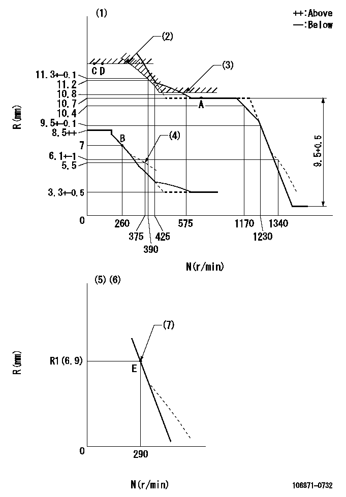
N:Pump speed
R:Rack position (mm)
(1)Tolerance for racks not indicated: +-0.05mm.
(2)Rack limit using stop lever: RA
(3)Excess fuel setting for starting: SXL
(4)Damper spring setting
(5)Variable speed specification: idling adjustment
(6)Fix the lever at the full-load position at delivery.
(7)Main spring setting
----------
RA=(13.3)+-0.1mm SXL=10.8+-0.1mm
----------
----------
RA=(13.3)+-0.1mm SXL=10.8+-0.1mm
----------
Speed control lever angle

F:Full speed
I:Idle
(1)Pump speed = aa
(2)Set the stopper bolt (fixed at full-load position at delivery.)
----------
aa=290r/min
----------
a=5deg+-5deg b=(11deg)+-5deg
----------
aa=290r/min
----------
a=5deg+-5deg b=(11deg)+-5deg
0000000901

F:Full load
I:Idle
(1)Stopper bolt setting
----------
----------
a=24.5deg+-5deg b=27.5deg+-3deg
----------
----------
a=24.5deg+-5deg b=27.5deg+-3deg
Stop lever angle
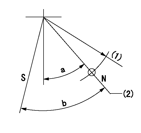
N:Pump normal
S:Stop the pump.
(1)R = aa
(2)Rack position bb
----------
aa=50mm bb=(13.3)+-0.1mm
----------
a=32.5deg+-5deg b=34.5deg+-5deg
----------
aa=50mm bb=(13.3)+-0.1mm
----------
a=32.5deg+-5deg b=34.5deg+-5deg
Timing setting
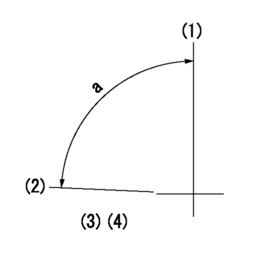
(1)Pump vertical direction
(2)Position of the coupling's key groove at the beginning of injection of the No. 8 cylinder.
(3)-
(4)-
----------
----------
a=(90deg)
----------
----------
a=(90deg)
Information:
Typical Example2. Remove eight bolts (3) that fasten pipe (1) to the elbow. Remove four bolts (2) that fasten the elbow to the aftercooler cover. Remove elbow (4).
Typical Example3. Remove bracket (5) from the oil filter tube and the oil level gauge group.
Typical Example4. Remove four bolts (7) from the air inlet elbow. Remove plate (6) and elbow (8). 5. Remove two tubes (10) from the air compressor to the aftercooler.6. Remove elbows (9) from the aftercooler housing.
Typical Example
Put identification on bolts (12) because they are 6.4 mm (.25 in) longer than all other bolts. They must be installed in the same location.
7. Remove bolts (11) and (12) from cover, and remove the cover.
Put identification on bolt (14) because it is 12.7 mm (.50 in) shorter than all the other bolts. It must be installed in the same location. Remove four adapters (15). Put plugs in both holes in the aftercooler core assembly. This will keep coolant out of the engine intake manifold.
8. Remove bolts (13) and (14) that hold the core assembly in position.9. Remove the aftercooler core assembly. 10. Remove air line (17) from the fuel ratio control valve.11. Remove eight bolts (16). Remove housing assembly (18).Install Aftercooler
1. Check all seals and gaskets for damage. If damaged, use new parts for replacement.
All foreign material and dirt must be removed from the gasket surface and inside the housing and intake manifold.
2. Install housing (1) and air line (2) to the fuel control valve. 3. Install four new seals (3) on the core assembly. Put clean glycerin on the O-ring seals. 4. Install core assembly (4) inside the housing. Remove plugs in both holes of the aftercooler core assembly. Install the bolts that fasten the core to housing. Install the bolts in their original location. 5. Put clean engine oil in the bores of the adapters. Install adapters (5). 6. Put cover (6) in position on the aftercooler. Install the two bolts in position (7). These bolts are 6.4 mm (.25 in) longer than all other bolts around the housing. Install the remainder of the bolts around the housing. 7. Install elbows (8). 8. Install two tubes (9) between the air compressor and the aftercooler.
Typical Example9. Install elbow (10) and plate (11) on the aftercooler cover. Install the bracket that is a support for the oil filter tube and the oil level gauge group. Install the oil filter tube and the oil level gauge group.
Typical Example10. Install eight bolts (13) that fasten the pipe to elbow (14). Install the elbow in the turbocharger.11. Install the four bolts that fasten the elbow to aftercooler cover (12).12. Fill the engine with coolant to the correct level. See the Operation & Maintenance Manual.
Have questions with 106871-0732?
Group cross 106871-0732 ZEXEL
106871-0732
INJECTION-PUMP ASSEMBLY

