Information injection-pump assembly
ZEXEL
106871-0590
1068710590
Rating:
Cross reference number
ZEXEL
106871-0590
1068710590
Zexel num
Bosch num
Firm num
Name
Calibration Data:
Adjustment conditions
Test oil
1404 Test oil ISO4113 or {SAEJ967d}
1404 Test oil ISO4113 or {SAEJ967d}
Test oil temperature
degC
40
40
45
Nozzle and nozzle holder
105780-8140
Bosch type code
EF8511/9A
Nozzle
105780-0000
Bosch type code
DN12SD12T
Nozzle holder
105780-2080
Bosch type code
EF8511/9
Opening pressure
MPa
17.2
Opening pressure
kgf/cm2
175
Injection pipe
Outer diameter - inner diameter - length (mm) mm 8-3-600
Outer diameter - inner diameter - length (mm) mm 8-3-600
Overflow valve opening pressure
kPa
157
123
191
Overflow valve opening pressure
kgf/cm2
1.6
1.25
1.95
Tester oil delivery pressure
kPa
157
157
157
Tester oil delivery pressure
kgf/cm2
1.6
1.6
1.6
Direction of rotation (viewed from drive side)
Right R
Right R
Injection timing adjustment
Direction of rotation (viewed from drive side)
Right R
Right R
Injection order
1-8-7-5-
4-3-6-2
Pre-stroke
mm
3.65
3.6
3.7
Beginning of injection position
Governor side NO.1
Governor side NO.1
Difference between angles 1
Cal 1-8 deg. 45 44.5 45.5
Cal 1-8 deg. 45 44.5 45.5
Difference between angles 2
Cal 1-7 deg. 90 89.5 90.5
Cal 1-7 deg. 90 89.5 90.5
Difference between angles 3
Cal 1-5 deg. 135 134.5 135.5
Cal 1-5 deg. 135 134.5 135.5
Difference between angles 4
Cal 1-4 deg. 180 179.5 180.5
Cal 1-4 deg. 180 179.5 180.5
Difference between angles 5
Cal 1-3 deg. 225 224.5 225.5
Cal 1-3 deg. 225 224.5 225.5
Difference between angles 6
Cal 1-6 deg. 270 269.5 270.5
Cal 1-6 deg. 270 269.5 270.5
Difference between angles 7
Cyl.1-2 deg. 315 314.5 315.5
Cyl.1-2 deg. 315 314.5 315.5
Injection quantity adjustment
Adjusting point
A
Rack position
10.3
Pump speed
r/min
650
650
650
Average injection quantity
mm3/st.
132.4
131.4
133.4
Max. variation between cylinders
%
0
-4
4
Basic
*
Fixing the lever
*
Injection quantity adjustment_02
Adjusting point
B
Rack position
6.6+-0.5
Pump speed
r/min
225
225
225
Average injection quantity
mm3/st.
13.6
11.6
15.6
Max. variation between cylinders
%
0
-10
10
Fixing the rack
*
Injection quantity adjustment_03
Adjusting point
C
Rack position
11.8+0.2
Pump speed
r/min
40
40
40
Average injection quantity
mm3/st.
115
105
125
Fixing the lever
*
Rack limit
*
Injection quantity adjustment_04
Adjusting point
D
Rack position
6.3+-0.5
Pump speed
r/min
325
325
325
Average injection quantity
mm3/st.
9
7
11
Fixing the rack
*
Timer adjustment
Pump speed
r/min
950--
Advance angle
deg.
0
0
0
Load
3/4
Remarks
Start
Start
Timer adjustment_02
Pump speed
r/min
900
Advance angle
deg.
0.5
Load
3/4
Timer adjustment_03
Pump speed
r/min
1100
Advance angle
deg.
4
3.5
4.5
Load
4/4
Remarks
Finish
Finish
Test data Ex:
Governor adjustment
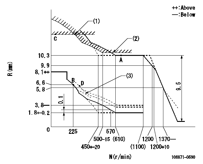
N:Pump speed
R:Rack position (mm)
(1)Rack limit using the stop lever: R1
(2)Excess fuel setting for starting: SXL
(3)Damper spring setting: DL
----------
R1=11.8+0.2mm SXL=10.3+0.2mm DL=5.6-0.2mm
----------
----------
R1=11.8+0.2mm SXL=10.3+0.2mm DL=5.6-0.2mm
----------
Speed control lever angle

F:Full speed
----------
----------
a=2deg+-5deg
----------
----------
a=2deg+-5deg
0000000901
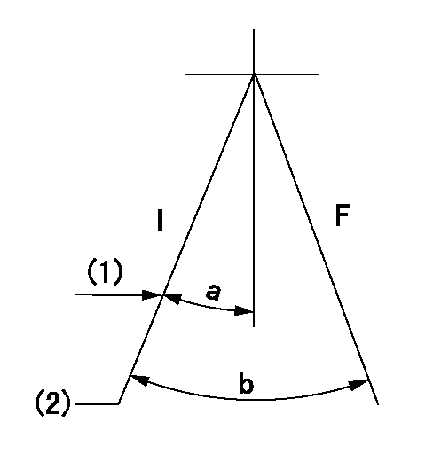
F:Full load
I:Idle
(1)Stopper bolt setting
(2)Set point B (at shipping)
----------
----------
a=24.5deg+-5deg b=31deg+-3deg
----------
----------
a=24.5deg+-5deg b=31deg+-3deg
Stop lever angle
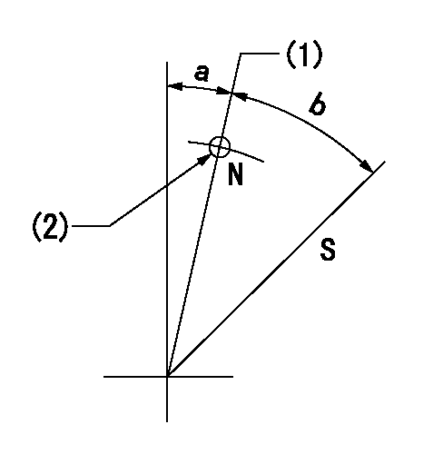
N:Pump normal
S:Stop the pump.
(1)Rack position = aa
(2)Use the hole at R = bb
----------
aa=11.8+0.2mm bb=32mm
----------
a=1deg+-5deg b=30.5deg+-5deg
----------
aa=11.8+0.2mm bb=32mm
----------
a=1deg+-5deg b=30.5deg+-5deg
Timing setting

(1)Pump vertical direction
(2)Position of the coupling's key groove at the beginning of injection of the No. 8 cylinder.
(3)-
(4)-
----------
----------
a=(90deg)
----------
----------
a=(90deg)
Information:
Start By:a. disassemble governorb. remove fuel injection pumps 1. Remove the six lifters from the fuel pump housing.2. Remove rack (1) and camshaft (2) from the fuel pump housing. If necessary, use a soft hammer to push the camshaft out the governor end. 3. Use Tool (A) and remove the three camshaft bearings from the fuel pump housing. 4. Remove rack bearing (4) and the other rack bearing from the fuel pump housing.5. Remove dowel (3) from the fuel pump housing. 6. Remove bolts (6), cover (5) and the gasket from the fuel pump housing.Assemble Fuel Injection Pump Housing
1. Install gasket (7) and cover (5) on the side of the fuel pump housing. 2. Use Tool (B) and install the D shaped rack bearing into the governor and fuel pump drive side of the fuel pump housing 87.0 0.5 mm (3.42 .02 in) from outside surface (X).3. The inside flat diameter after assembly must be 11.178 0.050 mm (.440 .002 in) and the inside large diameter must be 12.767 0.058 mm (.503 .002 in). 4. Install dowel (3) in the fuel pump housing 6.0 0.5 (.24 .02 in) above the outside surface.5. Use Tool (C) and install the rack bearing into the fuel pump housing 7.16 0.13 mm (.282 .005 in) below the surface of the pump housing.6. The inside diameter of the bearing after assembly must be 12.746 0.045 (.502 .002 in). 7. Use Tool (A) and install the three camshaft bearings in the fuel pump housing with the oil holes in the bearings 30 3 degrees from the horizontal center line toward the plugged holes in the fuel pump housing.8. The inside diameter of all three bearings after assembly must be 68.399 0.038 mm (2.6905 .0015 in). 9. Make sure bearing (8) on the governor and fuel pump drive is installed 1.0 0.5 mm (.04 .02 in) below surface (Y).10. Make sure middle bearing (9) is 218 0.3 mm (8.6 .01 in) below surface (Y). 11. Make sure bearing (10) governor side is 1.00 0.25 mm (.040 .010 in) below the outside surface.12. Remove the plugs from the side of the fuel pump housing. The oil holes in the bearings must in alignment with holes (11) in the fuel pump housing. If the bearings are not in alignment, remove them and install again. 13. Make an alignment of rack (1) and install it in the fuel pump housing.14. Install the six lifters in the fuel pump housing. Make sure the pins in the lifter are on the same side as the dowels in the fuel pump housing.End By:a. install fuel injection pumpsb. assemble governor
1. Install gasket (7) and cover (5) on the side of the fuel pump housing. 2. Use Tool (B) and install the D shaped rack bearing into the governor and fuel pump drive side of the fuel pump housing 87.0 0.5 mm (3.42 .02 in) from outside surface (X).3. The inside flat diameter after assembly must be 11.178 0.050 mm (.440 .002 in) and the inside large diameter must be 12.767 0.058 mm (.503 .002 in). 4. Install dowel (3) in the fuel pump housing 6.0 0.5 (.24 .02 in) above the outside surface.5. Use Tool (C) and install the rack bearing into the fuel pump housing 7.16 0.13 mm (.282 .005 in) below the surface of the pump housing.6. The inside diameter of the bearing after assembly must be 12.746 0.045 (.502 .002 in). 7. Use Tool (A) and install the three camshaft bearings in the fuel pump housing with the oil holes in the bearings 30 3 degrees from the horizontal center line toward the plugged holes in the fuel pump housing.8. The inside diameter of all three bearings after assembly must be 68.399 0.038 mm (2.6905 .0015 in). 9. Make sure bearing (8) on the governor and fuel pump drive is installed 1.0 0.5 mm (.04 .02 in) below surface (Y).10. Make sure middle bearing (9) is 218 0.3 mm (8.6 .01 in) below surface (Y). 11. Make sure bearing (10) governor side is 1.00 0.25 mm (.040 .010 in) below the outside surface.12. Remove the plugs from the side of the fuel pump housing. The oil holes in the bearings must in alignment with holes (11) in the fuel pump housing. If the bearings are not in alignment, remove them and install again. 13. Make an alignment of rack (1) and install it in the fuel pump housing.14. Install the six lifters in the fuel pump housing. Make sure the pins in the lifter are on the same side as the dowels in the fuel pump housing.End By:a. install fuel injection pumpsb. assemble governor