Information injection-pump assembly
ZEXEL
106871-0580
1068710580
Rating:
Service parts 106871-0580 INJECTION-PUMP ASSEMBLY:
1.
_
3.
GOVERNOR
7.
COUPLING PLATE
8.
_
9.
_
11.
Nozzle and Holder
16600-97064
12.
Open Pre:MPa(Kqf/cm2)
14.7{150}/21.6{220}

15.
NOZZLE SET
Include in #1:
106871-0580
as INJECTION-PUMP ASSEMBLY
Cross reference number
ZEXEL
106871-0580
1068710580
Zexel num
Bosch num
Firm num
Name
Calibration Data:
Adjustment conditions
Test oil
1404 Test oil ISO4113 or {SAEJ967d}
1404 Test oil ISO4113 or {SAEJ967d}
Test oil temperature
degC
40
40
45
Nozzle and nozzle holder
105780-8140
Bosch type code
EF8511/9A
Nozzle
105780-0000
Bosch type code
DN12SD12T
Nozzle holder
105780-2080
Bosch type code
EF8511/9
Opening pressure
MPa
17.2
Opening pressure
kgf/cm2
175
Injection pipe
Outer diameter - inner diameter - length (mm) mm 8-3-600
Outer diameter - inner diameter - length (mm) mm 8-3-600
Overflow valve opening pressure
kPa
157
123
191
Overflow valve opening pressure
kgf/cm2
1.6
1.25
1.95
Tester oil delivery pressure
kPa
157
157
157
Tester oil delivery pressure
kgf/cm2
1.6
1.6
1.6
Direction of rotation (viewed from drive side)
Right R
Right R
Injection timing adjustment
Direction of rotation (viewed from drive side)
Right R
Right R
Injection order
1-8-7-5-
4-3-6-2
Pre-stroke
mm
3.65
3.6
3.7
Beginning of injection position
Governor side NO.1
Governor side NO.1
Difference between angles 1
Cal 1-8 deg. 45 44.5 45.5
Cal 1-8 deg. 45 44.5 45.5
Difference between angles 2
Cal 1-7 deg. 90 89.5 90.5
Cal 1-7 deg. 90 89.5 90.5
Difference between angles 3
Cal 1-5 deg. 135 134.5 135.5
Cal 1-5 deg. 135 134.5 135.5
Difference between angles 4
Cal 1-4 deg. 180 179.5 180.5
Cal 1-4 deg. 180 179.5 180.5
Difference between angles 5
Cal 1-3 deg. 225 224.5 225.5
Cal 1-3 deg. 225 224.5 225.5
Difference between angles 6
Cal 1-6 deg. 270 269.5 270.5
Cal 1-6 deg. 270 269.5 270.5
Difference between angles 7
Cyl.1-2 deg. 315 314.5 315.5
Cyl.1-2 deg. 315 314.5 315.5
Injection quantity adjustment
Adjusting point
A
Rack position
10.3
Pump speed
r/min
650
650
650
Average injection quantity
mm3/st.
132.4
131.4
133.4
Max. variation between cylinders
%
0
-4
4
Basic
*
Fixing the lever
*
Injection quantity adjustment_02
Adjusting point
B
Rack position
6.6+-0.5
Pump speed
r/min
225
225
225
Average injection quantity
mm3/st.
13.6
11.6
15.6
Max. variation between cylinders
%
0
-10
10
Fixing the rack
*
Injection quantity adjustment_03
Adjusting point
D
Rack position
6.5+-0.5
Pump speed
r/min
290
290
290
Average injection quantity
mm3/st.
13.6
11.6
15.6
Fixing the rack
*
Timer adjustment
Pump speed
r/min
950--
Advance angle
deg.
0
0
0
Load
3/4
Remarks
Start
Start
Timer adjustment_02
Pump speed
r/min
900
Advance angle
deg.
0.5
Load
3/4
Timer adjustment_03
Pump speed
r/min
1100
Advance angle
deg.
4
3.5
4.5
Load
4/4
Remarks
Finish
Finish
Test data Ex:
Governor adjustment
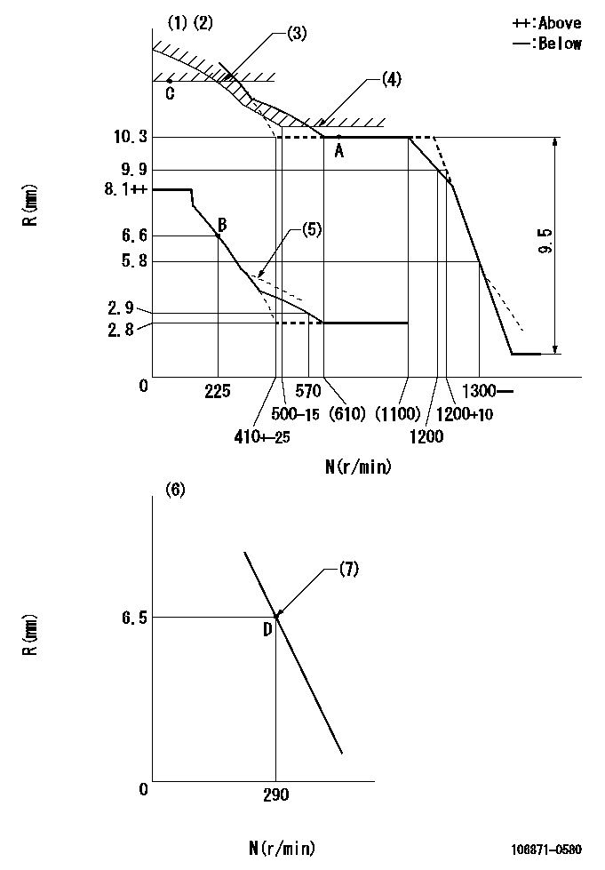
N:Pump speed
R:Rack position (mm)
(1)Lever ratio: RT
(2)Target shim dimension: TH
(3)Rack limit using the stop lever: R1
(4)Excess fuel setting for starting: SXL
(5)Damper spring setting: DL
(6)Variable speed specification: idling adjustment
(7)Main spring setting
----------
RT=1 TH=2.4mm R1=11.8+0.2mm SXL=10.3+0.2mm DL=5.6-0.2mm
----------
----------
RT=1 TH=2.4mm R1=11.8+0.2mm SXL=10.3+0.2mm DL=5.6-0.2mm
----------
Speed control lever angle

F:Full speed
I:Idle
(1)Stopper bolt setting
----------
----------
a=3deg+-5deg b=(15deg)+-5deg
----------
----------
a=3deg+-5deg b=(15deg)+-5deg
0000000901

F:Full load
I:Idle
(1)Stopper bolt setting
----------
----------
a=24.5deg+-5deg b=28deg+-3deg
----------
----------
a=24.5deg+-5deg b=28deg+-3deg
Stop lever angle

N:Pump normal
S:Stop the pump.
(1)Rack position = aa
----------
aa=11.8+0.2mm
----------
a=1.5deg+-5deg b=30.5deg+-5deg
----------
aa=11.8+0.2mm
----------
a=1.5deg+-5deg b=30.5deg+-5deg
Timing setting

(1)Pump vertical direction
(2)Position of the coupling's key groove at the beginning of injection of the No. 8 cylinder.
(3)-
(4)-
----------
----------
a=(90deg)
----------
----------
a=(90deg)
Information:
Typical Example1. Remove bolts (1) and cover (2). Remove bolts (3) and cover (4).
Typical Example2. Remove bolts (5) and adapter (6). Be sure that gear stays in place. Remove bolts (7) and cover (8). Keep gear in place.
Typical Example3. Remove gears (9) and crankshaft gear (10). Remove bolts (11) and idler gear (12) with retainer. Remove bolts (13) and idler gear (14) with retainer.
Typical Example4. Secure strap and a hoist to housing (15). Remove hose assembly (16) and small bolts (17) and large bolts (18). 5. Remove bolts (19) that connect housing to oil pan (20). Remove housing from cylinder block. The weight of housing is approximately 105 kg (230 lb). 6. Check O-ring seal (21) and bearing (22) on adapter and replace if necessary. 7. Check bearing (23) and O-ring seal (24) on cover and replace if necessary. 8. Remove retainer (25) from gear (9) and check bearings (26) and replace if necessary. The following steps are for the installation of the flywheel housing.9. Thoroughly clean the contact surfaces of the cylinder block and flywheel housing. Install a new gasket between the flywheel housing and the cylinder clock.10. Secure strap and a hoist to the flywheel housing, put flywheel housing in position on the cylinder block. 11. Install the bolts that hold the flywheel housing to the cylinder block. Tighten bolts 1 thru 22 in number sequence to a torque of 40 10 N m (30 7 lb ft). Tighten bolts 1 thru 9 in number sequence again to a torque of 135 20 N m (100 15 lb ft). Tighten bolts 10 thru 22 in number sequence again to a torque of 55 10 N m (40 7 lb ft).12. Install bolts that connect housing to oil pan.13. Cut flywheel housing gasket off even with the cylinder block surface. Remove excess sealant.End By:a. install crankshaft rear seal and wear sleeveb. install starting motor