Information injection-pump assembly
BOSCH
9 400 618 030
9400618030
ZEXEL
106871-0512
1068710512
NISSAN-DIESEL
1671397669
1671397669
Rating:
Cross reference number
BOSCH
9 400 618 030
9400618030
ZEXEL
106871-0512
1068710512
NISSAN-DIESEL
1671397669
1671397669
Zexel num
Bosch num
Firm num
Name
106871-0512
9 400 618 030
1671397669 NISSAN-DIESEL
INJECTION-PUMP ASSEMBLY
RE8 * K
RE8 * K
Calibration Data:
Adjustment conditions
Test oil
1404 Test oil ISO4113 or {SAEJ967d}
1404 Test oil ISO4113 or {SAEJ967d}
Test oil temperature
degC
40
40
45
Nozzle and nozzle holder
105780-8140
Bosch type code
EF8511/9A
Nozzle
105780-0000
Bosch type code
DN12SD12T
Nozzle holder
105780-2080
Bosch type code
EF8511/9
Opening pressure
MPa
17.2
Opening pressure
kgf/cm2
175
Injection pipe
Outer diameter - inner diameter - length (mm) mm 8-3-600
Outer diameter - inner diameter - length (mm) mm 8-3-600
Overflow valve opening pressure
kPa
157
123
191
Overflow valve opening pressure
kgf/cm2
1.6
1.25
1.95
Tester oil delivery pressure
kPa
157
157
157
Tester oil delivery pressure
kgf/cm2
1.6
1.6
1.6
Direction of rotation (viewed from drive side)
Right R
Right R
Injection timing adjustment
Direction of rotation (viewed from drive side)
Right R
Right R
Injection order
1-8-7-5-
4-3-6-2
Pre-stroke
mm
3.65
3.6
3.7
Beginning of injection position
Governor side NO.1
Governor side NO.1
Difference between angles 1
Cal 1-8 deg. 45 44.5 45.5
Cal 1-8 deg. 45 44.5 45.5
Difference between angles 2
Cal 1-7 deg. 90 89.5 90.5
Cal 1-7 deg. 90 89.5 90.5
Difference between angles 3
Cal 1-5 deg. 135 134.5 135.5
Cal 1-5 deg. 135 134.5 135.5
Difference between angles 4
Cal 1-4 deg. 180 179.5 180.5
Cal 1-4 deg. 180 179.5 180.5
Difference between angles 5
Cal 1-3 deg. 225 224.5 225.5
Cal 1-3 deg. 225 224.5 225.5
Difference between angles 6
Cal 1-6 deg. 270 269.5 270.5
Cal 1-6 deg. 270 269.5 270.5
Difference between angles 7
Cyl.1-2 deg. 315 314.5 315.5
Cyl.1-2 deg. 315 314.5 315.5
Injection quantity adjustment
Adjusting point
A
Rack position
10
Pump speed
r/min
700
700
700
Average injection quantity
mm3/st.
105.2
104.2
106.2
Max. variation between cylinders
%
0
-4
4
Basic
*
Fixing the lever
*
Injection quantity adjustment_02
Adjusting point
B
Rack position
6.3+-0.5
Pump speed
r/min
250
250
250
Average injection quantity
mm3/st.
12.9
10.9
14.9
Max. variation between cylinders
%
0
-10
10
Fixing the rack
*
Timer adjustment
Pump speed
r/min
750
Advance angle
deg.
0.5
Timer adjustment_02
Pump speed
r/min
900
Advance angle
deg.
1.4
0.9
1.9
Timer adjustment_03
Pump speed
r/min
1150
Advance angle
deg.
5.5
5
6
Remarks
Finish
Finish
Test data Ex:
Governor adjustment
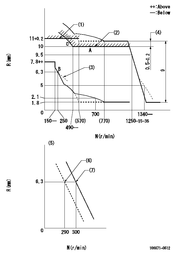
N:Pump speed
R:Rack position (mm)
(1)Rack limit using stop lever: R1 (at N = N1 or less).
(2)Excess fuel setting for starting
(3)Damper spring setting: DL
(4)At pump speed N2
(5)Variable speed specification: idling adjustment
(6)Main spring setting
(7)Set idle sub-spring
----------
N1=100r/min DL=6.3-0.2mm N2=1100r/min
----------
----------
N1=100r/min DL=6.3-0.2mm N2=1100r/min
----------
Speed control lever angle

F:Full speed
I:Idle
(1)Stopper bolt setting
(2)Set the stopper bolt (fixed at full-load position at delivery.)
----------
----------
a=(24deg)+-5deg b=(12deg)+-5deg
----------
----------
a=(24deg)+-5deg b=(12deg)+-5deg
0000000901
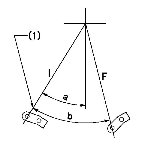
F:Full load
I:Idle
(1)Stopper bolt setting
----------
----------
a=24.5deg+-5deg b=31deg+-3deg
----------
----------
a=24.5deg+-5deg b=31deg+-3deg
Stop lever angle
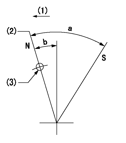
N:Pump normal
S:Stop the pump.
(1)Drive side
(2)Rack position = aa
(3)Use the hole at R = bb
----------
aa=11+0.2mm bb=32mm
----------
a=28.5deg+-5deg b=3deg+-5deg
----------
aa=11+0.2mm bb=32mm
----------
a=28.5deg+-5deg b=3deg+-5deg
Timing setting

(1)Pump vertical direction
(2)Position of the coupling's key groove at the beginning of injection of the No. 8 cylinder.
(3)-
(4)-
----------
----------
a=(90deg)
----------
----------
a=(90deg)
Information:
If the crankshaft is not in the correct position when the magnetic pickup sensor is installed, the magnetic probe will be damaged when the engine is started.
F. Put a 2D6392 O-Ring Seal on the end of the Magnetic Pick-up Sensor (a small amount of clean engine oil will let the seal slide onto the sensor more easily).G. Push the sensor through the adapter until it comes in contact with the counterweight and move the O-Ring Seal down against the adapter.H. Withdraw the sensor 1 mm (.04 in.) and hand tighten the nut on the adapter sleeve to firmly hold the timing probe in position.I. Connect cable for magnetic pick-up to the magnetic pick-up sensor. Step 2. Install ECAP And Injector HarnessA. Connect an ECAP to the Engine Data Link Connector (J8).B. Install the Injection "T" Harness on the Fuel Injector Connector (J5/P5) in the valve cover base.C. Be certain all connections (probe, harness, ECAP) are made correctly. Use special care when connecting "T" Harness to J5. The plug can be mis-aligned. Also use care when reconnecting J5 and P5. Incorrect installation will result in a "No Start" condition. Step 3. Calibrate Speed/Timing SensorA. Start the engine and run at low idle until the engine has warmed up enough to change out of Cold Mode operation. The "Diagnostic Lamp" should go out after the engine has started and the 10 second lamp test is complete. The engine rpm will decrease from approximately 1000 rpm while in the cold mode to the programmed low idle rpm when out of Cold Mode.B. Check for ACTIVE Diagnostic Codes. Use the procedures in this manual to troubleshoot and repair any ACTIVE Diagnostic Codes before attempting a calibration check.C. After engine has shifted out of Cold Mode, select the 3176 Timing Calibrate Screen on the ECAP. To insure the most accurate timing calibration, the engine rpm should be held as steady as possible at approximately 1500 rpm. This can be performed using the hand throttle. Any major changes (greater than 100 rpm) will slow down the procedure and make it less accurate.D. Press on the "space" key on the ECAP and wait until the ECAP indicates timing is CALIBRATED (approximately 15 seconds).E. Verify that timing has been calibrated by observing the "Desired Timing" bar display on the ECAP. Run the engine at different rpm's, allowing a few seconds at each setting for the rpm to stabilize. * If the ECAP display reads that injection timing is CALIBRATED, but during verification, the actual timing bar display is not within the two vertical timing tolerance lines and/or the display is erratic, repeat the timing calibration procedure.* If the ECAP display reads UNABLE TO CALIBRATE TIMING, the electronic injection timing has NOT been set. OK: Timing is functional and calibrated if the right end of the bar graph display stays within the vertical bars at all steady speeds. NOT OK: Recheck the tool installation and tool operation. Verify that the engine speeds were kept stable ( 50
Have questions with 106871-0512?
Group cross 106871-0512 ZEXEL
Nissan-Diesel
Nissan-Diesel
Nissan-Diesel
106871-0512
9 400 618 030
1671397669
INJECTION-PUMP ASSEMBLY
RE8
RE8