Information injection-pump assembly
ZEXEL
106871-0500
1068710500
NISSAN-DIESEL
1680097506
1680097506
Rating:
Cross reference number
ZEXEL
106871-0500
1068710500
NISSAN-DIESEL
1680097506
1680097506
Zexel num
Bosch num
Firm num
Name
Calibration Data:
Adjustment conditions
Test oil
1404 Test oil ISO4113 or {SAEJ967d}
1404 Test oil ISO4113 or {SAEJ967d}
Test oil temperature
degC
40
40
45
Nozzle and nozzle holder
105780-8140
Bosch type code
EF8511/9A
Nozzle
105780-0000
Bosch type code
DN12SD12T
Nozzle holder
105780-2080
Bosch type code
EF8511/9
Opening pressure
MPa
17.2
Opening pressure
kgf/cm2
175
Injection pipe
Outer diameter - inner diameter - length (mm) mm 8-3-600
Outer diameter - inner diameter - length (mm) mm 8-3-600
Overflow valve opening pressure
kPa
157
123
191
Overflow valve opening pressure
kgf/cm2
1.6
1.25
1.95
Tester oil delivery pressure
kPa
157
157
157
Tester oil delivery pressure
kgf/cm2
1.6
1.6
1.6
Direction of rotation (viewed from drive side)
Right R
Right R
Injection timing adjustment
Direction of rotation (viewed from drive side)
Right R
Right R
Injection order
1-8-7-5-
4-3-6-2
Pre-stroke
mm
3.65
3.6
3.7
Beginning of injection position
Governor side NO.1
Governor side NO.1
Difference between angles 1
Cal 1-8 deg. 45 44.5 45.5
Cal 1-8 deg. 45 44.5 45.5
Difference between angles 2
Cal 1-7 deg. 90 89.5 90.5
Cal 1-7 deg. 90 89.5 90.5
Difference between angles 3
Cal 1-5 deg. 135 134.5 135.5
Cal 1-5 deg. 135 134.5 135.5
Difference between angles 4
Cal 1-4 deg. 180 179.5 180.5
Cal 1-4 deg. 180 179.5 180.5
Difference between angles 5
Cal 1-3 deg. 225 224.5 225.5
Cal 1-3 deg. 225 224.5 225.5
Difference between angles 6
Cal 1-6 deg. 270 269.5 270.5
Cal 1-6 deg. 270 269.5 270.5
Difference between angles 7
Cyl.1-2 deg. 315 314.5 315.5
Cyl.1-2 deg. 315 314.5 315.5
Injection quantity adjustment
Adjusting point
A
Rack position
9.3
Pump speed
r/min
700
700
700
Average injection quantity
mm3/st.
111.5
110.5
112.5
Max. variation between cylinders
%
0
-4
4
Basic
*
Fixing the lever
*
Injection quantity adjustment_02
Adjusting point
B
Rack position
8.5
Pump speed
r/min
1200
1200
1200
Average injection quantity
mm3/st.
105.2
103.2
107.2
Max. variation between cylinders
%
0
-4
4
Fixing the lever
*
Injection quantity adjustment_03
Adjusting point
E
Rack position
6.3+-0.5
Pump speed
r/min
225
225
225
Average injection quantity
mm3/st.
9.4
7.4
11.4
Max. variation between cylinders
%
0
-10
10
Fixing the rack
*
Test data Ex:
Governor adjustment
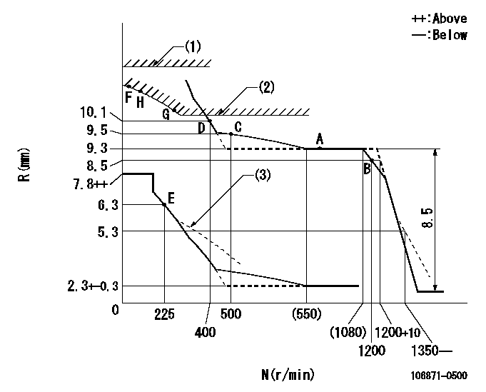
N:Pump speed
R:Rack position (mm)
(1)Rack limit using the stop lever: R1
(2)Excess fuel setting for starting: SXL
(3)Damper spring setting: DL
----------
R1=13.8+0.2mm SXL=10.1+-0.1mm DL=5.8-0.2mm
----------
----------
R1=13.8+0.2mm SXL=10.1+-0.1mm DL=5.8-0.2mm
----------
Timer adjustment

(1)Adjusting range
(2)Step response time
(N): Speed of the pump
(L): Load
(theta) Advance angle
(Srd1) Step response time 1
(Srd2) Step response time 2
1. Adjusting conditions for the variable timer
(1)Adjust the clearance between the pickup and the protrusion to L.
----------
L=1-0.2mm N4=800r/min C4=(7deg) t1=1.7--sec. t2=1.7--sec.
----------
N1=400r/min N2=1250++r/min N3=- C1=7+-0.3deg C2=3.5++deg C3=- P1=0kPa(0kgf/cm2) P2=294kPa(3kgf/cm2) P3=392kPa(4kgf/cm2) R01=0/4load R02=4/4load R03=4/4load
----------
L=1-0.2mm N4=800r/min C4=(7deg) t1=1.7--sec. t2=1.7--sec.
----------
N1=400r/min N2=1250++r/min N3=- C1=7+-0.3deg C2=3.5++deg C3=- P1=0kPa(0kgf/cm2) P2=294kPa(3kgf/cm2) P3=392kPa(4kgf/cm2) R01=0/4load R02=4/4load R03=4/4load
Speed control lever angle

F:Full speed
----------
----------
a=(1deg)+-5deg
----------
----------
a=(1deg)+-5deg
0000000901

F:Full load
I:Idle
(1)Stopper bolt setting
----------
----------
a=24.5deg+-5deg b=26deg+-3deg
----------
----------
a=24.5deg+-5deg b=26deg+-3deg
Stop lever angle
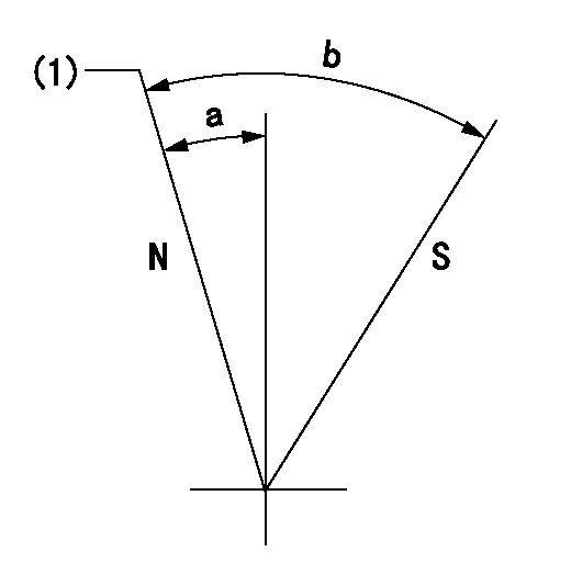
N:Pump normal
S:Stop the pump.
(1)Rack position = aa
----------
aa=13.8+0.2mm
----------
a=10.5deg+-5deg b=36deg+-5deg
----------
aa=13.8+0.2mm
----------
a=10.5deg+-5deg b=36deg+-5deg
0000001501 RACK SENSOR

(VR) measurement voltage
(I) Part number of the control unit
(G) Apply red paint.
(H): End surface of the pump
1. Rack sensor adjustment (-0620)
(1)Fix the speed control lever at the full position
(2)Set the speed to N1 r/min.
(If the boost compensator is provided, apply boost pressure.)
(3)Adjust the bobbin (A) so that the rack sensor's output voltage is VR+-0.01.
(4)At that time, rack position must be Ra.
(5)Apply G at two places.
Connecting part between the joint (B) and the nut (F)
Connecting part between the joint (B) and the end surface of the pump (H)
----------
N1=700r/min Ra=9.3mm
----------
----------
N1=700r/min Ra=9.3mm
----------
Timing setting

(1)Pump vertical direction
(2)Position of the coupling's key groove at the beginning of injection of the No. 8 cylinder.
(3)-
(4)-
----------
----------
a=(90deg)
----------
----------
a=(90deg)
Information:
Fuel Pressure Input Circuit
Fuel pressure is monitored after the filter by the fuel pressure sensor which is located on the fuel filter housing. The 5 Volt DC operating voltage for this sensor is supplied by the ECM. The output of the fuel pressure sensor is a .5 to 4.5 Volts DC signal. The voltage is dependent upon fuel pressure and is interpreted by the ECM as fuel pressure. If fuel pressure is less than 445 kPa (65 psi) at rated rpm, the "check engine" light is turned on.Engine Electrical System
The electrical system can have three separate circuits: the charging circuit, the starting circuit and the low amperage circuit. Some of the electrical system components are used in more than one circuit. The battery (batteries), circuit breaker, ammeter, cables and wires from the battery are all common in each of the circuits.The charging circuit is in operation when the engine is running. An alternator makes electricity for the charging circuit. A voltage regulator in the circuit controls the electrical output to keep the battery at full charge.The starting circuit is in operation only when the start switch is activated.The low amperage circuit and the charging circuit are both connected through the ammeter. The starting circuit is not connected through the ammeter.Charging System Components
Alternator
The alternator is driven by 2 vee belts from the crankshaft pulley. This alternator is a three phase, self-rectifying charging unit, and the regulator is part of the alternator.This alternator design has no need for slip rings or brushes, and the only part that has movement is the rotor assembly. All conductors that carry current are stationary. The conductors are: the field winding, stator windings, six rectifying diodes, and the regulator circuit components.The rotor assembly has many magnetic poles like fingers with air space between each opposite pole. The poles have residual magnetism (like permanent magnets) that produce a small amount of magnet-like lines of force (magnetic field) between the poles. As the rotor assembly begins to turn between the field winding and the stator windings, a small amount of alternating current (AC) is produced in the stator windings from the small magnetic lines of force made by the residual magnetism of the poles. This AC current is changed to direct current (DC) when it passes through the diodes of the rectifier bridge. Most of this current goes to charge the battery and to supply the low amperage circuit, and the remainder is sent on to the field windings. The DC current flow through the field windings (wires around an iron core) now increases the strength of the magnetic lines of force. These stronger lines of force now increase the amount of AC current produced in the stator windings. The increased speed of the rotor assembly also increases the current and voltage output of the alternator.The voltage regulator is a solid state (transistor, stationary parts) electronic switch. It feels the voltage in the system and switches on and off many times a second to control the field