Information injection-pump assembly
BOSCH
9 400 618 027
9400618027
ZEXEL
106871-0484
1068710484
NISSAN-DIESEL
1671397667
1671397667
Rating:
Cross reference number
BOSCH
9 400 618 027
9400618027
ZEXEL
106871-0484
1068710484
NISSAN-DIESEL
1671397667
1671397667
Zexel num
Bosch num
Firm num
Name
106871-0484
9 400 618 027
1671397667 NISSAN-DIESEL
INJECTION-PUMP ASSEMBLY
RF8 * K
RF8 * K
Calibration Data:
Adjustment conditions
Test oil
1404 Test oil ISO4113 or {SAEJ967d}
1404 Test oil ISO4113 or {SAEJ967d}
Test oil temperature
degC
40
40
45
Nozzle and nozzle holder
105780-8140
Bosch type code
EF8511/9A
Nozzle
105780-0000
Bosch type code
DN12SD12T
Nozzle holder
105780-2080
Bosch type code
EF8511/9
Opening pressure
MPa
17.2
Opening pressure
kgf/cm2
175
Injection pipe
Outer diameter - inner diameter - length (mm) mm 8-3-600
Outer diameter - inner diameter - length (mm) mm 8-3-600
Overflow valve opening pressure
kPa
157
123
191
Overflow valve opening pressure
kgf/cm2
1.6
1.25
1.95
Tester oil delivery pressure
kPa
157
157
157
Tester oil delivery pressure
kgf/cm2
1.6
1.6
1.6
Direction of rotation (viewed from drive side)
Right R
Right R
Injection timing adjustment
Direction of rotation (viewed from drive side)
Right R
Right R
Injection order
1-8-7-5-
4-3-6-2
Pre-stroke
mm
3.65
3.6
3.7
Beginning of injection position
Governor side NO.1
Governor side NO.1
Difference between angles 1
Cal 1-8 deg. 45 44.5 45.5
Cal 1-8 deg. 45 44.5 45.5
Difference between angles 2
Cal 1-7 deg. 90 89.5 90.5
Cal 1-7 deg. 90 89.5 90.5
Difference between angles 3
Cal 1-5 deg. 135 134.5 135.5
Cal 1-5 deg. 135 134.5 135.5
Difference between angles 4
Cal 1-4 deg. 180 179.5 180.5
Cal 1-4 deg. 180 179.5 180.5
Difference between angles 5
Cal 1-3 deg. 225 224.5 225.5
Cal 1-3 deg. 225 224.5 225.5
Difference between angles 6
Cal 1-6 deg. 270 269.5 270.5
Cal 1-6 deg. 270 269.5 270.5
Difference between angles 7
Cyl.1-2 deg. 315 314.5 315.5
Cyl.1-2 deg. 315 314.5 315.5
Injection quantity adjustment
Adjusting point
A
Rack position
10.3
Pump speed
r/min
650
650
650
Average injection quantity
mm3/st.
132.4
131.4
133.4
Max. variation between cylinders
%
0
-4
4
Basic
*
Fixing the lever
*
Injection quantity adjustment_02
Adjusting point
B
Rack position
6.6+-0.5
Pump speed
r/min
225
225
225
Average injection quantity
mm3/st.
13.6
11.6
15.6
Max. variation between cylinders
%
0
-10
10
Fixing the rack
*
Injection quantity adjustment_03
Adjusting point
C
Rack position
11.8+0.2
Pump speed
r/min
40
40
40
Average injection quantity
mm3/st.
115
105
125
Fixing the lever
*
Rack limit
*
Injection quantity adjustment_04
Adjusting point
D
Rack position
6.5+-0.5
Pump speed
r/min
290
290
290
Average injection quantity
mm3/st.
13.6
11.6
15.6
Fixing the rack
*
Timer adjustment
Pump speed
r/min
950--
Advance angle
deg.
0
0
0
Load
3/4
Remarks
Start
Start
Timer adjustment_02
Pump speed
r/min
900
Advance angle
deg.
0.5
Load
3/4
Timer adjustment_03
Pump speed
r/min
1100
Advance angle
deg.
4
3.5
4.5
Load
4/4
Remarks
Finish
Finish
Test data Ex:
Governor adjustment
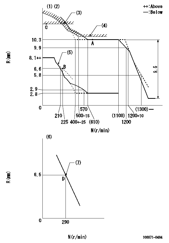
N:Pump speed
R:Rack position (mm)
(1)Lever ratio: RT
(2)Target shim dimension: TH
(3)Rack limit using the stop lever: R1
(4)Excess fuel setting for starting: SXL
(5)Damper spring setting: DL
(6)Variable speed specification: idling adjustment
(7)Main spring setting
----------
RT=1 TH=2.4mm R1=11.8+0.2mm SXL=10.3+0.2mm DL=(7.1)mm
----------
----------
RT=1 TH=2.4mm R1=11.8+0.2mm SXL=10.3+0.2mm DL=(7.1)mm
----------
Speed control lever angle

F:Full speed
I:Idle
(1)Stopper bolt setting
----------
----------
a=11deg+-5deg b=(21deg)+-5deg
----------
----------
a=11deg+-5deg b=(21deg)+-5deg
0000000901

F:Full load
I:Idle
(1)Stopper bolt setting
----------
----------
a=24.5deg+-5deg b=28deg+-3deg
----------
----------
a=24.5deg+-5deg b=28deg+-3deg
Stop lever angle
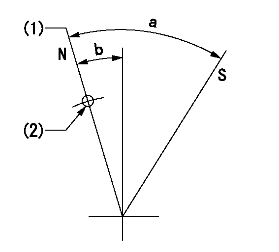
N:Pump normal
S:Stop the pump.
(1)Rack position = aa
(2)Use the hole at R = bb
----------
aa=11.8+0.2mm bb=32mm
----------
a=30.5deg+-5deg b=1.5deg+-5deg
----------
aa=11.8+0.2mm bb=32mm
----------
a=30.5deg+-5deg b=1.5deg+-5deg
Timing setting

(1)Pump vertical direction
(2)Position of the coupling's key groove at the beginning of injection of the No. 8 cylinder.
(3)-
(4)-
----------
----------
a=(90deg)
----------
----------
a=(90deg)
Information:
Intake and exhaust valve stems are to be coated with 8T2998 Breakin Lubricant prior to installation in the cylinder head.(1) Intake valve.(2) Exhaust valve.(3) Height to top of valve guide ... 28.00 0.05 mm (1.102 .002 in)(4) Outer Valve Spring (7W7082): Assembled length ... 51.69 mm (2.035 in)Load at assembled length ... 240 24 N (54 5 lb)Operating length (min) ... 37.72 mm (1.485 in)Load at min operating length ... 650 32 N (146 7 lb)Free length after test ... 59.89 mm (2.358 in)Outside diameter ... 34.00 mm (1.339 in)(5) Inner Valve Spring (7W7083): Assembled length ... 49.19 mm (1.937 in)Load at assembled length ... 136 14 N (31 3 lb)Operating length (min) ... 35.22 mm (1.387 in)Load at min operating length ... 292 15 N (66 3 lb)Free length after test ... 61.39 mm (2.417 in)Outside diameter ... 23.24 mm (.915 in)(6) Diameter of valve stems (new) ... 9.441 0.008 mm (.3717 .0003 in)Use again minimum:7C1586 Exhaust ... 9.408 mm (.3704 in)7C5215 Intake ... 9.408 mm (.3704 in)Bore in valve guide with guide installed in the head (new) ... 9.484 0.026 mm (.3734 .0010 in)Use again dimension for valve guide bore ... 9.538 mm (.3755 in)(7) Diameter of valve head: Exhaust valve ... 42.00 0.13 mm (1.654 .005 in)Intake valve ... 45.00 0.13 mm (1.772 .005 in)(8) Angle of valve face: Angle of intake valve face ... 29 1/4 1/4°Angle of exhaust valve face ... 44 1/4 1/4° (9) Depth of bore in head for valve seat insert: Intake ... 15.00 0.10 mm (.591 .004 in)Exhaust ... 14.10 0.10 mm (.555 .004 in) Inserts to be shrunk by reduced temperature before being placed in counterbore.(10) Diameter of valve seat insert for intake valve ... 46.025 0.013 mm (1.8120 .0005 in) Bore in head for valve seat insert for intake valve ... 45.950 0.025 mm (1.8091 .0010 in)Diameter of valve seat insert for exhaust valve ... 43.400 0.015 mm (1.7086 .0006 in)Bore in head for valve seat insert for exhaust valve ... 43.320 0.025 mm (1.7055 .0009 in)(11) Angle of face of intake valve seat insert ... 30 1/4 1/2°Angle of face of exhaust valve seat insert ... 44 3/4 1/2°(12) "Use again" thickness of valve lip: Exhaust valve ... 2.03 mm (.080 in)Intake valve ... 2.51 mm (.099 in)
Have questions with 106871-0484?
Group cross 106871-0484 ZEXEL
Nissan-Diesel
Nissan-Diesel
Nissan-Diesel
Nissan-Diesel
Nissan-Diesel
Nissan-Diesel
Nissan-Diesel
106871-0484
9 400 618 027
1671397667
INJECTION-PUMP ASSEMBLY
RF8
RF8