Information injection-pump assembly
ZEXEL
106871-0480
1068710480
Rating:
Cross reference number
ZEXEL
106871-0480
1068710480
Zexel num
Bosch num
Firm num
Name
Calibration Data:
Adjustment conditions
Test oil
1404 Test oil ISO4113 or {SAEJ967d}
1404 Test oil ISO4113 or {SAEJ967d}
Test oil temperature
degC
40
40
45
Nozzle and nozzle holder
105780-8140
Bosch type code
EF8511/9A
Nozzle
105780-0000
Bosch type code
DN12SD12T
Nozzle holder
105780-2080
Bosch type code
EF8511/9
Opening pressure
MPa
17.2
Opening pressure
kgf/cm2
175
Injection pipe
Outer diameter - inner diameter - length (mm) mm 8-3-600
Outer diameter - inner diameter - length (mm) mm 8-3-600
Overflow valve opening pressure
kPa
157
123
191
Overflow valve opening pressure
kgf/cm2
1.6
1.25
1.95
Tester oil delivery pressure
kPa
157
157
157
Tester oil delivery pressure
kgf/cm2
1.6
1.6
1.6
Direction of rotation (viewed from drive side)
Right R
Right R
Injection timing adjustment
Direction of rotation (viewed from drive side)
Right R
Right R
Injection order
1-8-7-5-
4-3-6-2
Pre-stroke
mm
3.65
3.6
3.7
Beginning of injection position
Governor side NO.1
Governor side NO.1
Difference between angles 1
Cal 1-8 deg. 45 44.5 45.5
Cal 1-8 deg. 45 44.5 45.5
Difference between angles 2
Cal 1-7 deg. 90 89.5 90.5
Cal 1-7 deg. 90 89.5 90.5
Difference between angles 3
Cal 1-5 deg. 135 134.5 135.5
Cal 1-5 deg. 135 134.5 135.5
Difference between angles 4
Cal 1-4 deg. 180 179.5 180.5
Cal 1-4 deg. 180 179.5 180.5
Difference between angles 5
Cal 1-3 deg. 225 224.5 225.5
Cal 1-3 deg. 225 224.5 225.5
Difference between angles 6
Cal 1-6 deg. 270 269.5 270.5
Cal 1-6 deg. 270 269.5 270.5
Difference between angles 7
Cyl.1-2 deg. 315 314.5 315.5
Cyl.1-2 deg. 315 314.5 315.5
Injection quantity adjustment
Adjusting point
A
Rack position
10.3
Pump speed
r/min
650
650
650
Average injection quantity
mm3/st.
132.4
131.4
133.4
Max. variation between cylinders
%
0
-4
4
Basic
*
Fixing the lever
*
Injection quantity adjustment_02
Adjusting point
B
Rack position
6.6+-0.5
Pump speed
r/min
225
225
225
Average injection quantity
mm3/st.
13.6
11.6
15.6
Max. variation between cylinders
%
0
-10
10
Fixing the rack
*
Injection quantity adjustment_03
Adjusting point
C
Rack position
11.8+0.2
Pump speed
r/min
40
40
40
Average injection quantity
mm3/st.
115
105
125
Fixing the lever
*
Rack limit
*
Injection quantity adjustment_04
Adjusting point
D
Rack position
6.5+-0.5
Pump speed
r/min
290
290
290
Average injection quantity
mm3/st.
13.6
11.6
15.6
Fixing the rack
*
Timer adjustment
Pump speed
r/min
950--
Advance angle
deg.
0
0
0
Load
3/4
Remarks
Start
Start
Timer adjustment_02
Pump speed
r/min
900
Advance angle
deg.
0.5
Load
3/4
Timer adjustment_03
Pump speed
r/min
1100
Advance angle
deg.
4
3.5
4.5
Load
4/4
Remarks
Finish
Finish
Test data Ex:
Governor adjustment
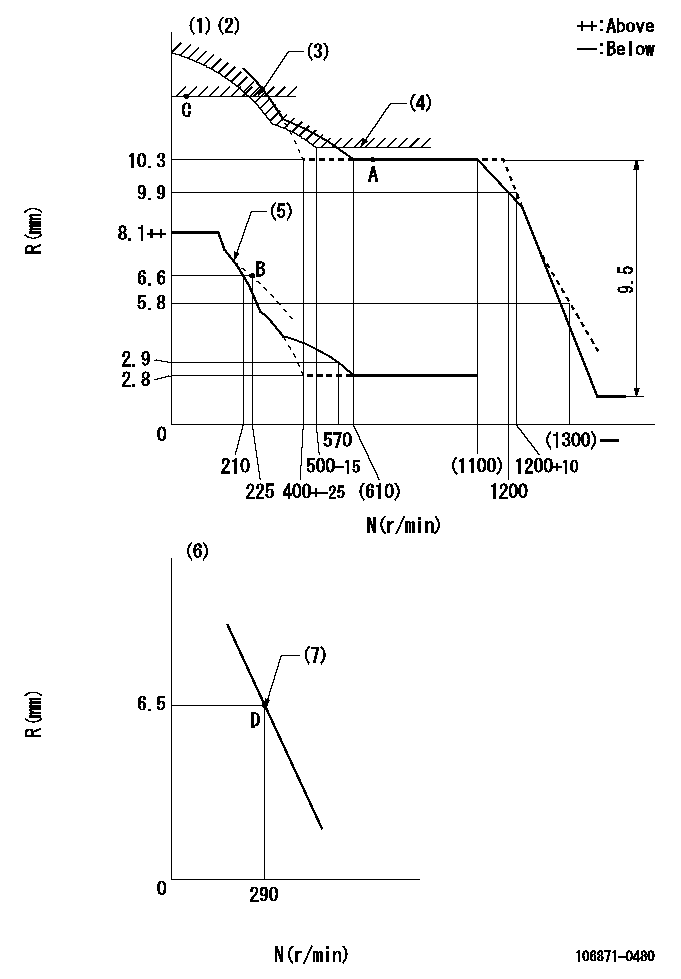
N:Pump speed
R:Rack position (mm)
(1)Lever ratio: RT
(2)Target shim dimension: TH
(3)Rack limit using the stop lever: R1
(4)Excess fuel setting for starting: SXL
(5)Damper spring setting: DL
(6)Variable speed specification: idling adjustment
(7)Main spring setting
----------
RT=1 TH=2.4mm R1=11.8+0.2mm SXL=10.3+0.2mm DL=(7.1)mm
----------
----------
RT=1 TH=2.4mm R1=11.8+0.2mm SXL=10.3+0.2mm DL=(7.1)mm
----------
Speed control lever angle

F:Full speed
I:Idle
(1)Stopper bolt setting
----------
----------
a=11deg+-5deg b=(21deg)+-5deg
----------
----------
a=11deg+-5deg b=(21deg)+-5deg
0000000901

F:Full load
I:Idle
(1)Stopper bolt setting
----------
----------
a=24.5deg+-5deg b=28deg+-3deg
----------
----------
a=24.5deg+-5deg b=28deg+-3deg
Stop lever angle
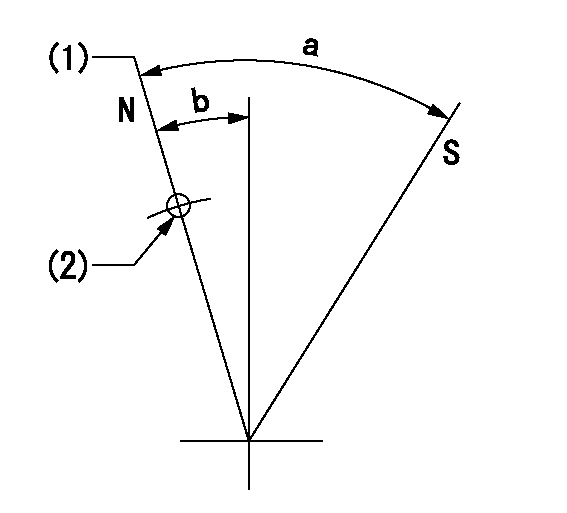
N:Pump normal
S:Stop the pump.
(1)Rack position = aa
(2)Use the hole at R = bb
----------
aa=11.8+0.2mm bb=32mm
----------
a=30.5deg+-5deg b=1.5deg+-5deg
----------
aa=11.8+0.2mm bb=32mm
----------
a=30.5deg+-5deg b=1.5deg+-5deg
Timing setting

(1)Pump vertical direction
(2)Position of the coupling's key groove at the beginning of injection of the No. 8 cylinder.
(3)-
(4)-
----------
----------
a=(90deg)
----------
----------
a=(90deg)
Information:
1. Fasten a dial indicator to the crankshaft flange so the anvil of the indicator will touch the face of the flywheel housing.2. Force the crankshaft toward the rear before an indication is taken on the indicator at each point. 3. With dial indicator set at "0" (zero) at location (A), turn the crankshaft and read the indicator at locations (B), (C) and (D).4. The difference between lower and higher measurements taken at all four points must not be more than 0.20 mm (.008 in.)Bore Runout
Write the dial indicator measurements with their positive (+) and negative (-) notation (signs). This notation is necessary when the calculations are made in the chart correctly. 1. Fasten a dial indicator to the crankshaft flange so the 7H1940 Universal Attachment of the indicator is in contact with the inner flywheel housing bore at location (C). Adjust the dial indicator to "0" (zero). Push the crankshaft up against the top crankshaft bearing. Write the measurement for bearing clearance on line 1 in column (C) of the chart.2. Divide the measurement from Step 1 by 2. Write this number on line in columns (B) and (D). 3. Turn the crankshaft to put the dial indicator at (A). Adjust the dial indicator to "0" (zero).4. Turn the crankshaft counterclockwise to put the dial indicator at (B). Write the measurement in the chart.5. Turn the crankshaft counterclockwise to put the dial indicator at (C). Write the measurement in the chart.6. Turn the crankshaft counterclockwise to put the dial indicator at (D). Write the measurement in the chart.7. Add lines I and II by columns. 8. Subtract the smaller number from the larger number in line II in columns (B) and (D). The result is the horizontal "eccentricity" (out of round). Line III, column (C) is the vertical eccentricity. 9. On the graph for total eccentricity, find the point of intersection of the lines for vertical eccentricity and horizontal eccentricity.10. If the point of intersection is in the range marked "Acceptable" the bore is in alignment. If the point of intersection is in the range marked "Not Acceptable", the flywheel housing must be changed.
Write the dial indicator measurements with their positive (+) and negative (-) notation (signs). This notation is necessary when the calculations are made in the chart correctly. 1. Fasten a dial indicator to the crankshaft flange so the 7H1940 Universal Attachment of the indicator is in contact with the inner flywheel housing bore at location (C). Adjust the dial indicator to "0" (zero). Push the crankshaft up against the top crankshaft bearing. Write the measurement for bearing clearance on line 1 in column (C) of the chart.2. Divide the measurement from Step 1 by 2. Write this number on line in columns (B) and (D). 3. Turn the crankshaft to put the dial indicator at (A). Adjust the dial indicator to "0" (zero).4. Turn the crankshaft counterclockwise to put the dial indicator at (B). Write the measurement in the chart.5. Turn the crankshaft counterclockwise to put the dial indicator at (C). Write the measurement in the chart.6. Turn the crankshaft counterclockwise to put the dial indicator at (D). Write the measurement in the chart.7. Add lines I and II by columns. 8. Subtract the smaller number from the larger number in line II in columns (B) and (D). The result is the horizontal "eccentricity" (out of round). Line III, column (C) is the vertical eccentricity. 9. On the graph for total eccentricity, find the point of intersection of the lines for vertical eccentricity and horizontal eccentricity.10. If the point of intersection is in the range marked "Acceptable" the bore is in alignment. If the point of intersection is in the range marked "Not Acceptable", the flywheel housing must be changed.