Information injection-pump assembly
ZEXEL
106871-0431
1068710431
Rating:
Cross reference number
ZEXEL
106871-0431
1068710431
Zexel num
Bosch num
Firm num
Name
106871-0431
NISSAN-DIESEL
INJECTION-PUMP ASSEMBLY
RE8 *
RE8 *
Calibration Data:
Adjustment conditions
Test oil
1404 Test oil ISO4113 or {SAEJ967d}
1404 Test oil ISO4113 or {SAEJ967d}
Test oil temperature
degC
40
40
45
Nozzle and nozzle holder
105780-8140
Bosch type code
EF8511/9A
Nozzle
105780-0000
Bosch type code
DN12SD12T
Nozzle holder
105780-2080
Bosch type code
EF8511/9
Opening pressure
MPa
17.2
Opening pressure
kgf/cm2
175
Injection pipe
Outer diameter - inner diameter - length (mm) mm 8-3-600
Outer diameter - inner diameter - length (mm) mm 8-3-600
Overflow valve opening pressure
kPa
157
123
191
Overflow valve opening pressure
kgf/cm2
1.6
1.25
1.95
Tester oil delivery pressure
kPa
157
157
157
Tester oil delivery pressure
kgf/cm2
1.6
1.6
1.6
Direction of rotation (viewed from drive side)
Right R
Right R
Injection timing adjustment
Direction of rotation (viewed from drive side)
Right R
Right R
Injection order
1-8-7-5-
4-3-6-2
Pre-stroke
mm
3.65
3.6
3.7
Beginning of injection position
Governor side NO.1
Governor side NO.1
Difference between angles 1
Cal 1-8 deg. 45 44.5 45.5
Cal 1-8 deg. 45 44.5 45.5
Difference between angles 2
Cal 1-7 deg. 90 89.5 90.5
Cal 1-7 deg. 90 89.5 90.5
Difference between angles 3
Cal 1-5 deg. 135 134.5 135.5
Cal 1-5 deg. 135 134.5 135.5
Difference between angles 4
Cal 1-4 deg. 180 179.5 180.5
Cal 1-4 deg. 180 179.5 180.5
Difference between angles 5
Cal 1-3 deg. 225 224.5 225.5
Cal 1-3 deg. 225 224.5 225.5
Difference between angles 6
Cal 1-6 deg. 270 269.5 270.5
Cal 1-6 deg. 270 269.5 270.5
Difference between angles 7
Cyl.1-2 deg. 315 314.5 315.5
Cyl.1-2 deg. 315 314.5 315.5
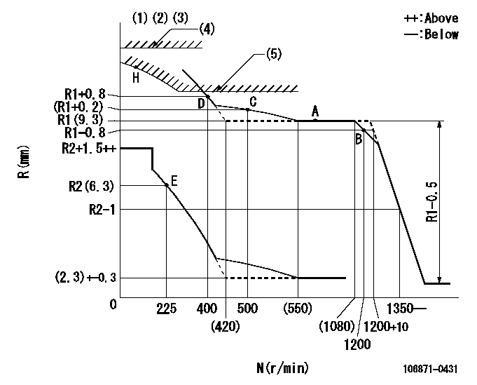
Injection quantity adjustment
Adjusting point
A
Rack position
R1(9.3)
Pump speed
r/min
700
700
700
Average injection quantity
mm3/st.
111.5
110.5
112.5
Max. variation between cylinders
%
0
-4
4
Basic
*
Fixing the lever
*
Injection quantity adjustment_02
Adjusting point
B
Rack position
R1-0.8
Pump speed
r/min
1200
1200
1200
Average injection quantity
mm3/st.
105.2
103.2
107.2
Max. variation between cylinders
%
0
-4
4
Fixing the lever
*
Injection quantity adjustment_03
Adjusting point
E
Rack position
R2(6.3)
Pump speed
r/min
225
225
225
Average injection quantity
mm3/st.
9.4
7.4
11.4
Max. variation between cylinders
%
0
-10
10
Fixing the rack
*
Injection quantity adjustment_04
Adjusting point
H
Rack position
-
Pump speed
r/min
100
100
100
Average injection quantity
mm3/st.
84
84
Fixing the lever
*
Timer adjustment
Pump speed
r/min
800--
Advance angle
deg.
0
0
0
Remarks
Start
Start
Timer adjustment_02
Pump speed
r/min
750
Advance angle
deg.
0.5
Timer adjustment_03
Pump speed
r/min
900
Advance angle
deg.
1.4
0.9
1.9
Timer adjustment_04
Pump speed
r/min
1150
Advance angle
deg.
5.5
5
6
Remarks
Finish
Finish
Test data Ex:
Governor adjustment
N:Pump speed
R:Rack position (mm)
(1)Lever ratio: RT
(2)Target shim dimension: TH
(3)Supplied with damper spring not set.
(4)Rack limit using stop lever: RA (at N = N1 or less).
(5)Excess fuel setting for starting: SXL
----------
RT=1 TH=2.3mm RA=R1+5.1+0.2mm N1=100r/min SXL=R1+0.8+0.2mm
----------
----------
RT=1 TH=2.3mm RA=R1+5.1+0.2mm N1=100r/min SXL=R1+0.8+0.2mm
----------
Speed control lever angle

F:Full speed
----------
----------
a=(14deg)+-5deg
----------
----------
a=(14deg)+-5deg
0000000901

F:Full load
I:Idle
(1)Stopper bolt setting
----------
----------
a=24.5deg+-5deg b=(26deg)+-3deg
----------
----------
a=24.5deg+-5deg b=(26deg)+-3deg
Stop lever angle
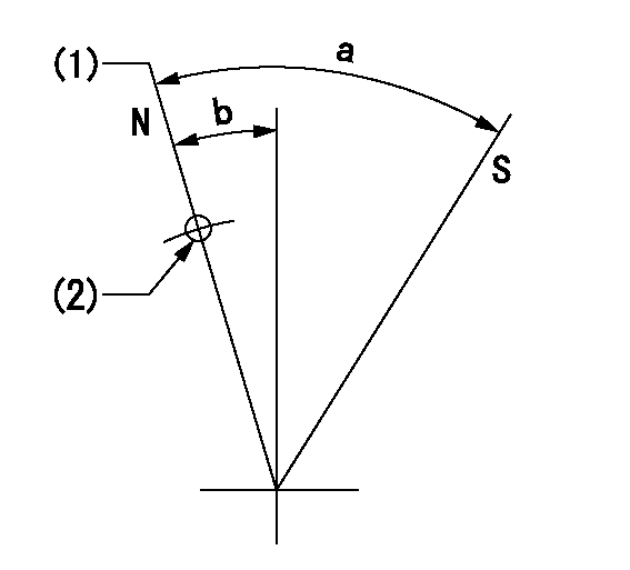
N:Pump normal
S:Stop the pump.
(1)Rack position = aa
(2)R = bb
----------
aa=R1+5.1+0.2mm bb=32mm
----------
a=(38deg)+-5deg b=(12.5deg)+-5deg
----------
aa=R1+5.1+0.2mm bb=32mm
----------
a=(38deg)+-5deg b=(12.5deg)+-5deg
Timing setting

(1)Pump vertical direction
(2)Position of the coupling's key groove at the beginning of injection of the No. 8 cylinder.
(3)-
(4)-
----------
----------
a=(90deg)
----------
----------
a=(90deg)
Information:
Flangeless Liners
(1) Outside diameter of cylinder liner ... 103.264 to 103.289 mm (4.0655 to 4.0665 in)(2) Inside diameter of cylinder liners ... 98.48 to 98.50 mm (3.877 to 3.878 in) Maximum diameter wear (when boring or new liners are needed) ... 0.20 mm (.008 in)Interference fit of liner in cylinder block ... 0.08 to 0.13 mm (.003 to .005 in)Length of cylinder liner ... 228.73 to 228.98 mm (9.005 to 9.015 in)Maximum cylinder liner can be bored (made larger than original size) ... 0.76 mm (.030 in) The flangeless cylinder liners are the only ones that can be bored. All other liners must be replaced when worn beyond specifications. The five ring pistons are the only ones offered in oversize.(3) Liner projection (height of liner above face of cylinder block) ... 0.71 to 0.94 mm (.028 to .037 in)(4) Diameter of bore in cylinder block for liner ... 103.162 to 103.188 mm (4.0615 to 4.0625 in)Flanged Liners
New cylinder blocks have been introduced on 4.236 and T4.236 engin s. They have a larger cylinder liner parent bore diameter and the outside diameter of the cylinder liner is also larger. The liners will no longer have a flame ring. Effective with this change, only flanged liners will be available. The change became effective at engine serial number LD or LJ----- U106654N and up. The engine serial number is located above the fuel injection pump on the block.(1) Outside diameter of cylinder linerEarlier engines with thin wall liners: Production liner ... 103.238 to 103.264 mm (4.0645 to 4.0655 in)Service Liner ... 103.188 to 103.213 mm (4.0625 to 4.0635 in)Current engines with thick wall liners: Production liner ... 104.254 to 104.280 mm (4.1045 to 4.1055 in)Service liner ... 104.204 to 104.229 mm (4.1025 to 4.1035 in)(2) Inside diameter of cylinder liner: Production liner ... 98.48 to 98.50 mm (3.877 to 3.878 in)Service liner ... 98.50 to 98.53 mm (3.878 to 3.879 in)Maximum diameter wear (when new liners are needed) ... 0.20 mm (.008 in)Transition fit of service liner in cylinder block ... 0.03 mm ( .001 in)Length of cylinder liner ... 227.10 to 227.43 mm (8.941 to 8.954 in)(3) Liner (flange) projection [do not measure projection from flange ring (if equipped)] ... 0.10 mm (.004 in) above to ... 0.10 mm (.004 in) below face of cylinder block. Flange thickness of cylinder liner ... 3.81 to 3.86 mm (.150 to .152 in)(4) Diameter of parent bore in cylinder block for liner: Earlier engines with thin wall liners ... 103.188 to 103.213 mm (4.0625 to 4.0635 in)Current engines with thick wall liners ... 104.204 to 104.229 mm (4.1025 to 4.1035 in)Depth of recess for cylinder liner flange ... 3.81 to 3.91 mm (.150 to .154 in)All Engine Blocks
(5) Diameter of bore in cylinder block
Have questions with 106871-0431?
Group cross 106871-0431 ZEXEL
Nissan-Diesel
106871-0431
INJECTION-PUMP ASSEMBLY
RE8
RE8