Information injection-pump assembly
ZEXEL
106871-0420
1068710420
Rating:
Cross reference number
ZEXEL
106871-0420
1068710420
Zexel num
Bosch num
Firm num
Name
Calibration Data:
Adjustment conditions
Test oil
1404 Test oil ISO4113 or {SAEJ967d}
1404 Test oil ISO4113 or {SAEJ967d}
Test oil temperature
degC
40
40
45
Nozzle and nozzle holder
105780-8140
Bosch type code
EF8511/9A
Nozzle
105780-0000
Bosch type code
DN12SD12T
Nozzle holder
105780-2080
Bosch type code
EF8511/9
Opening pressure
MPa
17.2
Opening pressure
kgf/cm2
175
Injection pipe
Outer diameter - inner diameter - length (mm) mm 8-3-600
Outer diameter - inner diameter - length (mm) mm 8-3-600
Overflow valve opening pressure
kPa
157
123
191
Overflow valve opening pressure
kgf/cm2
1.6
1.25
1.95
Tester oil delivery pressure
kPa
157
157
157
Tester oil delivery pressure
kgf/cm2
1.6
1.6
1.6
Direction of rotation (viewed from drive side)
Right R
Right R
Injection timing adjustment
Direction of rotation (viewed from drive side)
Right R
Right R
Injection order
1-8-7-5-
4-3-6-2
Pre-stroke
mm
3.65
3.6
3.7
Beginning of injection position
Governor side NO.1
Governor side NO.1
Difference between angles 1
Cal 1-8 deg. 45 44.5 45.5
Cal 1-8 deg. 45 44.5 45.5
Difference between angles 2
Cal 1-7 deg. 90 89.5 90.5
Cal 1-7 deg. 90 89.5 90.5
Difference between angles 3
Cal 1-5 deg. 135 134.5 135.5
Cal 1-5 deg. 135 134.5 135.5
Difference between angles 4
Cal 1-4 deg. 180 179.5 180.5
Cal 1-4 deg. 180 179.5 180.5
Difference between angles 5
Cal 1-3 deg. 225 224.5 225.5
Cal 1-3 deg. 225 224.5 225.5
Difference between angles 6
Cal 1-6 deg. 270 269.5 270.5
Cal 1-6 deg. 270 269.5 270.5
Difference between angles 7
Cyl.1-2 deg. 315 314.5 315.5
Cyl.1-2 deg. 315 314.5 315.5
Injection quantity adjustment
Adjusting point
A
Rack position
10.3
Pump speed
r/min
650
650
650
Average injection quantity
mm3/st.
132.4
131.4
133.4
Max. variation between cylinders
%
0
-4
4
Basic
*
Fixing the lever
*
Injection quantity adjustment_02
Adjusting point
B
Rack position
6.6+-0.5
Pump speed
r/min
225
225
225
Average injection quantity
mm3/st.
13.6
11.6
15.6
Max. variation between cylinders
%
0
-10
10
Fixing the rack
*
Injection quantity adjustment_03
Adjusting point
C
Rack position
11.8+0.2
Pump speed
r/min
40
40
40
Average injection quantity
mm3/st.
115
105
125
Fixing the lever
*
Rack limit
*
Test data Ex:
Governor adjustment
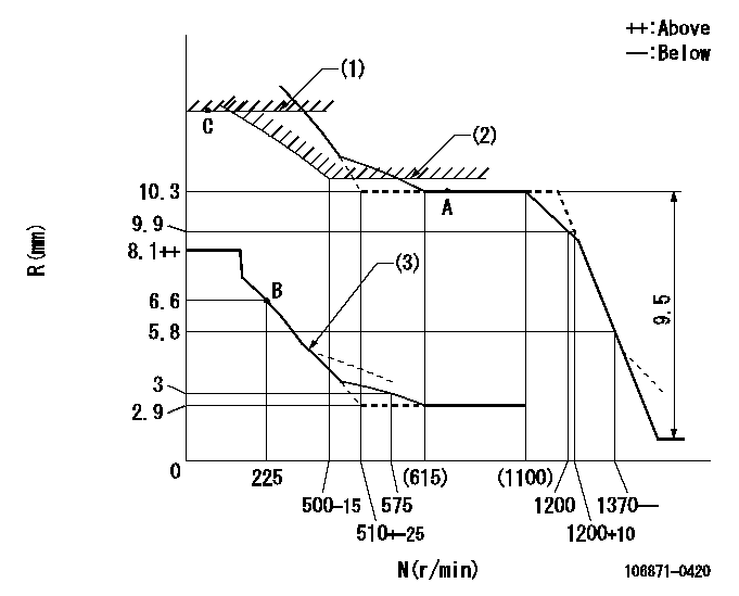
N:Pump speed
R:Rack position (mm)
(1)Rack limit using the stop lever: R1
(2)Excess fuel setting for starting: SXL
(3)Damper spring setting: DL
----------
R1=11.8+0.2mm SXL=10.3+0.2mm DL=5.6-0.2mm
----------
----------
R1=11.8+0.2mm SXL=10.3+0.2mm DL=5.6-0.2mm
----------
Timer adjustment

(1)Adjusting range
(2)Step response time
(N): Speed of the pump
(L): Load
(theta) Advance angle
(Srd1) Step response time 1
(Srd2) Step response time 2
1. Adjusting conditions for the variable timer
(1)Adjust the clearance between the pickup and the protrusion to L.
----------
L=1-0.2mm N2=800r/min C2=(7)deg t1=1.7--sec. t2=1.7--sec.
----------
N1=1250++r/min P1=0kPa(0kgf/cm2) P2=392kPa(4kgf/cm2) C1=7+-0.3deg R01=0/4load R02=4/4load
----------
L=1-0.2mm N2=800r/min C2=(7)deg t1=1.7--sec. t2=1.7--sec.
----------
N1=1250++r/min P1=0kPa(0kgf/cm2) P2=392kPa(4kgf/cm2) C1=7+-0.3deg R01=0/4load R02=4/4load
Speed control lever angle

F:Full speed
----------
----------
a=15deg+-5deg
----------
----------
a=15deg+-5deg
0000000901

F:Full load
I:Idle
(1)Stopper bolt setting
----------
----------
a=24.5deg+-5deg b=27.5deg+-3deg
----------
----------
a=24.5deg+-5deg b=27.5deg+-3deg
Stop lever angle
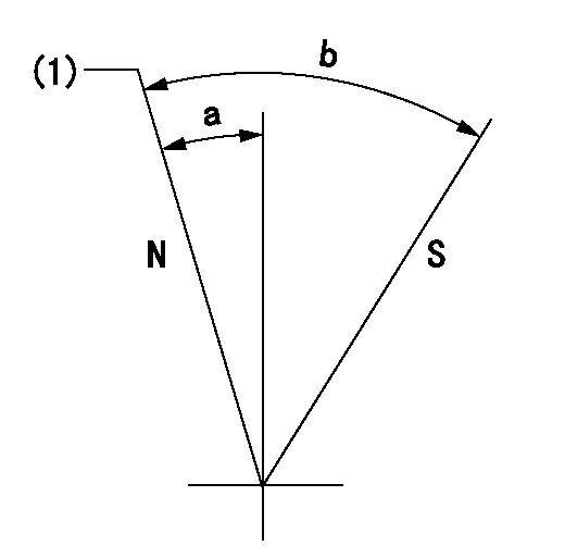
N:Pump normal
S:Stop the pump.
(1)Rack position = aa
----------
aa=11.8+0.2mm
----------
a=1.5deg+-5deg b=30.5deg+-5deg
----------
aa=11.8+0.2mm
----------
a=1.5deg+-5deg b=30.5deg+-5deg
0000001501 RACK SENSOR

(VR) measurement voltage
(I) Part number of the control unit
(G) Apply red paint.
(H): End surface of the pump
1. Rack sensor adjustment (-0620)
(1)Fix the speed control lever at the full position
(2)Set the speed to N1 r/min.
(If the boost compensator is provided, apply boost pressure.)
(3)Adjust the bobbin (A) so that the rack sensor's output voltage is VR+-0.01.
(4)At that time, rack position must be Ra.
(5)Apply G at two places.
Connecting part between the joint (B) and the nut (F)
Connecting part between the joint (B) and the end surface of the pump (H)
----------
N1=650r/min Ra=10.3mm
----------
----------
N1=650r/min Ra=10.3mm
----------
Timing setting

(1)Pump vertical direction
(2)Position of the coupling's key groove at the beginning of injection of the No. 8 cylinder.
(3)-
(4)-
----------
----------
a=(90deg)
----------
----------
a=(90deg)
Information:
3306 New Scroll Fuel System (NSFS) Hydraulic Actuator
The variable power actuator is mounted to the rear of the governor housing, where the shutoff solenoid is normally mounted. The actuator rod may be in one of two positions -- extended or retracted. The extended position limits the fuel rack travel to the lower power fuel setting. The retracted position allows the fuel rack to travel to the higher power fuel setting. By limiting the travel of the fuel rack, the fuel being injected into the engine is controlled. Fuel being injected into the engine determines the output power of the engine. The position of the actuator rod is determined by the gear engaged in the transmission of the applicable vehicle.High Power Range
Typical Variable Power Arrangement
1. Manifold. 2. Solenoid control valve. 3. Variable power actuator. 4. Governor control lever. 5. Transmission. 6. Switch.An electric switch (6) is mounted in the transmission (5). The transmission (5) is shifted into a gear where the higher power range is allowed. A transmission interlock pin causes the normally open switch (6) to close. When switch (6) is closed, it energizes solenoid control valve (2). The energized solenoid control valve (2) allows engine lube oil (under normal engine lube oil pressure) to flow through manifold (1) and into actuator (3).
Governor And Actuator
3. Actuator. 7. Oil inlet/outlet port. 11. Governor servo valve. 12. Lever. 13. Governor control shaft. 14. Actuator rod.The engine oil coming in port (7) compresses spring (15) and moves actuator rod (14) to the RETRACTED position. The RETRACTED actuator rod (14) allows the fuel rack more travel in the FUEL ON direction by a mechanical linkage through the governor servo valve (11) and lever (12). The fuel rack travel is now limited by the fuel setting screw.The actuator rod (14) will remain in the RETRACTED position as long as solenoid control valve (2) is energized. A light on the operator's console indicates when the engine is operating in the higher power range.
Governor And Variable Power Actuator (Retracted Position7. Oil inlet/outlet port.8. Washered adjusting