Information injection-pump assembly
BOSCH
9 400 618 022
9400618022
ZEXEL
106871-0415
1068710415
NISSAN-DIESEL
1671397663
1671397663
Rating:
Service parts 106871-0415 INJECTION-PUMP ASSEMBLY:
1.
_

7.
COUPLING PLATE
8.
_
9.
_
11.
Nozzle and Holder
1660097064
12.
Open Pre:MPa(Kqf/cm2)
14.7(150)/21.6(220)

15.
NOZZLE SET
Include in #1:
106871-0415
as INJECTION-PUMP ASSEMBLY
Cross reference number
BOSCH
9 400 618 022
9400618022
ZEXEL
106871-0415
1068710415
NISSAN-DIESEL
1671397663
1671397663
Zexel num
Bosch num
Firm num
Name
106871-0415
9 400 618 022
1671397663 NISSAN-DIESEL
INJECTION-PUMP ASSEMBLY
RF8 * K
RF8 * K
Calibration Data:
Adjustment conditions
Test oil
1404 Test oil ISO4113 or {SAEJ967d}
1404 Test oil ISO4113 or {SAEJ967d}
Test oil temperature
degC
40
40
45
Nozzle and nozzle holder
105780-8140
Bosch type code
EF8511/9A
Nozzle
105780-0000
Bosch type code
DN12SD12T
Nozzle holder
105780-2080
Bosch type code
EF8511/9
Opening pressure
MPa
17.2
Opening pressure
kgf/cm2
175
Injection pipe
Outer diameter - inner diameter - length (mm) mm 8-3-600
Outer diameter - inner diameter - length (mm) mm 8-3-600
Overflow valve opening pressure
kPa
157
123
191
Overflow valve opening pressure
kgf/cm2
1.6
1.25
1.95
Tester oil delivery pressure
kPa
157
157
157
Tester oil delivery pressure
kgf/cm2
1.6
1.6
1.6
Direction of rotation (viewed from drive side)
Right R
Right R
Injection timing adjustment
Direction of rotation (viewed from drive side)
Right R
Right R
Injection order
1-8-7-5-
4-3-6-2
Pre-stroke
mm
3.65
3.6
3.7
Beginning of injection position
Governor side NO.1
Governor side NO.1
Difference between angles 1
Cal 1-8 deg. 45 44.5 45.5
Cal 1-8 deg. 45 44.5 45.5
Difference between angles 2
Cal 1-7 deg. 90 89.5 90.5
Cal 1-7 deg. 90 89.5 90.5
Difference between angles 3
Cal 1-5 deg. 135 134.5 135.5
Cal 1-5 deg. 135 134.5 135.5
Difference between angles 4
Cal 1-4 deg. 180 179.5 180.5
Cal 1-4 deg. 180 179.5 180.5
Difference between angles 5
Cal 1-3 deg. 225 224.5 225.5
Cal 1-3 deg. 225 224.5 225.5
Difference between angles 6
Cal 1-6 deg. 270 269.5 270.5
Cal 1-6 deg. 270 269.5 270.5
Difference between angles 7
Cyl.1-2 deg. 315 314.5 315.5
Cyl.1-2 deg. 315 314.5 315.5
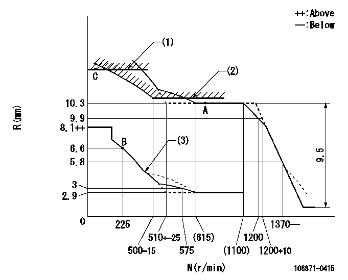
Injection quantity adjustment
Adjusting point
A
Rack position
10.3
Pump speed
r/min
650
650
650
Average injection quantity
mm3/st.
132.4
131.4
133.4
Max. variation between cylinders
%
0
-4
4
Basic
*
Fixing the lever
*
Injection quantity adjustment_02
Adjusting point
B
Rack position
6.6+-0.5
Pump speed
r/min
225
225
225
Average injection quantity
mm3/st.
13.6
11.6
15.6
Max. variation between cylinders
%
0
-10
10
Fixing the rack
*
Injection quantity adjustment_03
Adjusting point
C
Rack position
11.8+0.2
Pump speed
r/min
40
40
40
Average injection quantity
mm3/st.
115
105
125
Fixing the lever
*
Rack limit
*
Timer adjustment
Pump speed
r/min
950--
Advance angle
deg.
0
0
0
Load
3/4
Remarks
Start
Start
Timer adjustment_02
Pump speed
r/min
900
Advance angle
deg.
0.5
Load
3/4
Timer adjustment_03
Pump speed
r/min
1100
Advance angle
deg.
4
3.5
4.5
Load
4/4
Remarks
Finish
Finish
Test data Ex:
Governor adjustment
N:Pump speed
R:Rack position (mm)
(1)Rack limit using the stop lever: R1
(2)Excess fuel setting for starting: SXL
(3)Damper spring setting: DL
----------
R1=11.8+0.2mm SXL=10.3+0.2mm DL=5.6-0.2mm
----------
----------
R1=11.8+0.2mm SXL=10.3+0.2mm DL=5.6-0.2mm
----------
Speed control lever angle

F:Full speed
----------
----------
a=2deg+-5deg
----------
----------
a=2deg+-5deg
0000000901
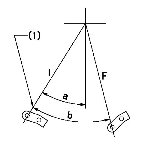
F:Full load
I:Idle
(1)Stopper bolt setting
----------
----------
a=24.5deg+-5deg b=27.5deg+-3deg
----------
----------
a=24.5deg+-5deg b=27.5deg+-3deg
Stop lever angle
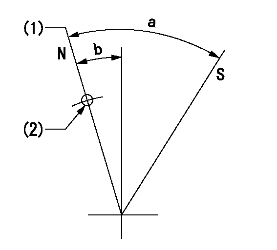
N:Pump normal
S:Stop the pump.
(1)Rack position = aa
(2)Use the hole at R = bb
----------
aa=11.8+0.2mm bb=32mm
----------
a=30.5deg+-5deg b=1.5deg+-5deg
----------
aa=11.8+0.2mm bb=32mm
----------
a=30.5deg+-5deg b=1.5deg+-5deg
Timing setting

(1)Pump vertical direction
(2)Position of the coupling's key groove at the beginning of injection of the No. 8 cylinder.
(3)-
(4)-
----------
----------
a=(90deg)
----------
----------
a=(90deg)
Information:
3306 New Scroll Fuel System (NSFS)
See the service manual for your engine for other adjusting procedures.
Rack Adjustment For Engines With NSFS
Rear Of Governor
1. Opening for variable power actuator.1. Remove the variable power actuator from the rear of the governor.2. Adjust the high power fuel setting using the standard fuel system setting procedure in the service manual.For the correct fuel setting specifications, see the Engine Information Plate or the FUEL SETTING AND RELATED INFORMATION FICHE.
6V7941 Compressor Assembly
Governor And Compressor
2. 6V7941 Compressor Assembly.3. Remove the 6V7941 Compressor Assembly (2) and replace the plug in the rear of the governor housing.
Variable Power Actuator
3. Rod. 4. Washered nut. 5. Jam nut. 6. Dust cover.4. Remove the dust cover (6) from the variable power actuator. Loosen the jam nut (5) on the rod (3). Tighten the washered nut (4) to put rod (3) in the fully retracted position.
Governor And Actuator
3. Rod. 4. Washered nut. 5. Jam nut. 7. Actuator.5. Install actuator (7) in governor housing opening (1).6. Move the governor control to the high idle position and hold or fasten the governor control in this position.7. Extend the actuator rod (3), by loosening the washered nut (4), to achieve a minimum dial indicator reading of 2.0 mm (.08 in.) less than the desired low power fuel setting.EXAMPLE: If the low power rack adjustment specification is 3.0 mm (.12 in.), the actuator rod (3) must be adjusted to obtain a dial indicator reading of 1.0 mm (.04 in.).8. Tighten the washered nut (4), to retract the actuator rod (3) and increase the dial indicator reading to the specified low power fuel setting.For the correct fuel setting specifications, see the Engine Information Plate or the FUEL SETTING AND RELATED INFORMATION FICHE.9. If the low power fuel setting is exceeded, repeat steps 7 and 8.10. Tighten the jam nut (5) on the actuator rod (3) and install the dust cover (6).3304 SMFS Air Only Actuator
See the service manual for your engine for other testing and adjusting procedures.
Rack Adjustment For Engines With Sleeve Metering Fuel System (SMFS)
1. Remove the variable power actuator (1) from the rear of the governor (2).2. Use the fuel setting procedure in the service manual and adjust the high power fuel setting screw.For the correct fuel setting specifications, see the Engine Information Plate or the FUEL SETTING AND RELATED INFORMATION FICHE.3. Install the variable power actuator (1).4. Remove the back cover (6) from the actuator (1) to expose the adjustment pin (5).5. Move the governor control shaft to the high idle position.6. Turn the adjustment pin (5) clockwise to adjust the variable power control rod (8) to the fully EXTENDED position.7. To adjust the low power setting, turn the adjustment pin (5) counterclockwise to retract rod (8). Retract the rod (8) until the rack setting is decreased to the specified setting.For the correct fuel setting specifications, see the Engine Information Plate or the FUEL SETTING AND RELATED INFORMATION FICHE.8. Replace cover (6) on the variable power actuator (6).
Governor And Variable Power Actuator
1. Variable
Have questions with 106871-0415?
Group cross 106871-0415 ZEXEL
Nissan-Diesel
Nissan-Diesel
106871-0415
9 400 618 022
1671397663
INJECTION-PUMP ASSEMBLY
RF8
RF8