Information injection-pump assembly
BOSCH
9 400 618 019
9400618019
ZEXEL
106871-0363
1068710363
NISSAN-DIESEL
1671397661
1671397661
Rating:
Cross reference number
BOSCH
9 400 618 019
9400618019
ZEXEL
106871-0363
1068710363
NISSAN-DIESEL
1671397661
1671397661
Zexel num
Bosch num
Firm num
Name
106871-0363
9 400 618 019
1671397661 NISSAN-DIESEL
INJECTION-PUMP ASSEMBLY
RE8 * K
RE8 * K
Calibration Data:
Adjustment conditions
Test oil
1404 Test oil ISO4113 or {SAEJ967d}
1404 Test oil ISO4113 or {SAEJ967d}
Test oil temperature
degC
40
40
45
Nozzle and nozzle holder
105780-8140
Bosch type code
EF8511/9A
Nozzle
105780-0000
Bosch type code
DN12SD12T
Nozzle holder
105780-2080
Bosch type code
EF8511/9
Opening pressure
MPa
17.2
Opening pressure
kgf/cm2
175
Injection pipe
Outer diameter - inner diameter - length (mm) mm 8-3-600
Outer diameter - inner diameter - length (mm) mm 8-3-600
Overflow valve opening pressure
kPa
157
123
191
Overflow valve opening pressure
kgf/cm2
1.6
1.25
1.95
Tester oil delivery pressure
kPa
157
157
157
Tester oil delivery pressure
kgf/cm2
1.6
1.6
1.6
Direction of rotation (viewed from drive side)
Right R
Right R
Injection timing adjustment
Direction of rotation (viewed from drive side)
Right R
Right R
Injection order
1-8-7-5-
4-3-6-2
Pre-stroke
mm
3.65
3.6
3.7
Beginning of injection position
Governor side NO.1
Governor side NO.1
Difference between angles 1
Cal 1-8 deg. 45 44.5 45.5
Cal 1-8 deg. 45 44.5 45.5
Difference between angles 2
Cal 1-7 deg. 90 89.5 90.5
Cal 1-7 deg. 90 89.5 90.5
Difference between angles 3
Cal 1-5 deg. 135 134.5 135.5
Cal 1-5 deg. 135 134.5 135.5
Difference between angles 4
Cal 1-4 deg. 180 179.5 180.5
Cal 1-4 deg. 180 179.5 180.5
Difference between angles 5
Cal 1-3 deg. 225 224.5 225.5
Cal 1-3 deg. 225 224.5 225.5
Difference between angles 6
Cal 1-6 deg. 270 269.5 270.5
Cal 1-6 deg. 270 269.5 270.5
Difference between angles 7
Cyl.1-2 deg. 315 314.5 315.5
Cyl.1-2 deg. 315 314.5 315.5
Injection quantity adjustment
Adjusting point
A
Rack position
9.2
Pump speed
r/min
1200
1200
1200
Average injection quantity
mm3/st.
99
97
101
Max. variation between cylinders
%
0
-4
4
Fixing the lever
*
Injection quantity adjustment_02
Adjusting point
B
Rack position
10
Pump speed
r/min
700
700
700
Average injection quantity
mm3/st.
105.2
104.2
106.2
Max. variation between cylinders
%
0
-4
4
Basic
*
Fixing the lever
*
Injection quantity adjustment_03
Adjusting point
D
Rack position
6.3+-0.5
Pump speed
r/min
250
250
250
Average injection quantity
mm3/st.
12.9
10.9
14.9
Max. variation between cylinders
%
0
-10
10
Fixing the rack
*
Timer adjustment
Pump speed
r/min
750
Advance angle
deg.
0.5
Timer adjustment_02
Pump speed
r/min
900
Advance angle
deg.
1.4
0.9
1.9
Timer adjustment_03
Pump speed
r/min
1150
Advance angle
deg.
5.5
5
6
Remarks
Finish
Finish
Test data Ex:
Governor adjustment
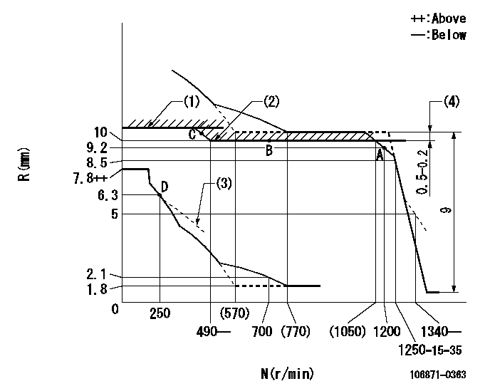
N:Pump speed
R:Rack position (mm)
(1)Rack limit using stop lever: R1 (at N = N1 or less).
(2)Excess fuel setting for starting
(3)Damper spring setting: DL
(4)Rack difference to N = N2
----------
R1=11+0.2mm N1=100r/min DL=6.3-0.2mm N2=1000r/min
----------
----------
R1=11+0.2mm N1=100r/min DL=6.3-0.2mm N2=1000r/min
----------
Speed control lever angle

F:Full speed
----------
----------
a=12deg+-5deg
----------
----------
a=12deg+-5deg
0000000901
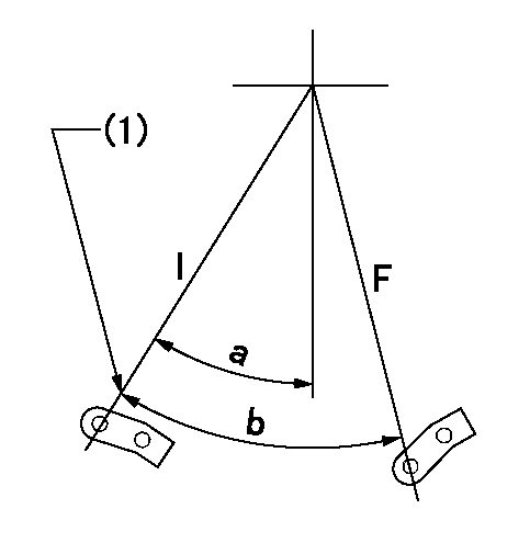
F:Full load
I:Idle
(1)Stopper bolt setting
----------
----------
a=24.5deg+-5deg b=31deg+-3deg
----------
----------
a=24.5deg+-5deg b=31deg+-3deg
Stop lever angle
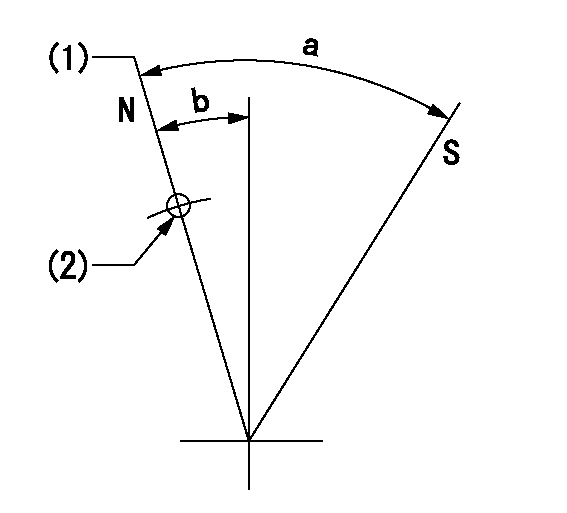
N:Pump normal
S:Stop the pump.
(1)Rack position = aa
(2)Use the hole at R = bb
----------
aa=11+0.2mm bb=32mm
----------
a=28.5deg+-5deg b=3deg+-5deg
----------
aa=11+0.2mm bb=32mm
----------
a=28.5deg+-5deg b=3deg+-5deg
Timing setting

(1)Pump vertical direction
(2)Position of the coupling's key groove at the beginning of injection of the No. 8 cylinder.
(3)-
(4)-
----------
----------
a=(90deg)
----------
----------
a=(90deg)
Information:
7N9720 Alternator 24V 35A (Bosch Number 0-122-469-001); 9G9538 Alternator 24V 50A (Bosch Number 0-122-469-002)
7N9720 AlternatorThe solid state regulator used with the Bosch Alternator is totally enclosed and non-adjustable. If the rate of charge is not correct a replacement of the regulator is necessary.9G4574 24V 35A (Nippondenso Number 100211-0860); 6T7223 24V 50A (Nippondenso Number 100211-0890)
9G4574 AlternatorNo adjustment can be made to change the rate of charge on the alternator regulator. If rate of charge is not correct, a replacement of the regulator is necessary.2P1204 24V 15A (Prestolite Number ANB-7004)
Prestolite Alternator Regulator
1. Adjustment screw. 2. High output position. 3. Green wire to field terminal of alternator. 4. Low output position. 5. Orange wire to field supply terminal.The regulator components are sealed in an insulation of epoxy. The regulator is an electronic component with no moving parts (solid state) and has an adjustment screw (1) on the back. This voltage adjustment screw is used to meet different needs of operation at different times of the year. To increase or decrease by .5 volts from the normal (N) setting, remove the regulator and change the position of the adjustment screw and pointer. Move the adjustment screw (1) and pointer to "H" position (2) to increase the voltage. Move adjustment screw (1) and pointer to "L" position (4) to decrease the voltage.Starting System
Use the multimeter in the DCV range to find starting system components which do not function.Move the start control switch to activate the starter solenoid. Starter solenoid operation can be heard as the pinion of the starter motor is engaged with the ring gear on the engine flywheel.If the solenoid for the starter motor will not operate, it is possible that the current from the battery did not get to the solenoid. Fasten one lead of the multimeter to the connection (terminal) for the battery cable on the solenoid. Put the other lead to a good ground. A zero reading is an indication that there is a broken circuit from the battery. More testing is necessary when there is a voltage reading on the multimeter.The solenoid operation also closes the electric circuit to the motor. Connect one lead of the multimeter to the solenoid connection (terminal) that is fastened to the motor. Put the other lead to a good ground. Activate the starter solenoid and look at the multimeter. A reading of battery voltage shows the problem is in the motor. The motor must be removed for further testing. A zero reading on the multimeter shows that the solenoid contacts do not close. This is an indication of the need for repair to the solenoid or an adjustment to be made to the starter pinion clearance.Make a test with one multimeter lead fastened to the connection (terminal) for the small wire at the solenoid and the other lead to the ground. Look at the multimeter and activate the starter solenoid. A voltage reading shows that the problem is in the solenoid. A zero reading is an indication that the problem is
Have questions with 106871-0363?
Group cross 106871-0363 ZEXEL
Nissan-Diesel
Nissan-Diesel
Nissan-Diesel
Nissan-Diesel
Nissan-Diesel
Nissan-Diesel
Nissan-Diesel
106871-0363
9 400 618 019
1671397661
INJECTION-PUMP ASSEMBLY
RE8
RE8