Information injection-pump assembly
BOSCH
9 400 618 018
9400618018
ZEXEL
106871-0322
1068710322
NISSAN-DIESEL
1671397616
1671397616
Rating:
Cross reference number
BOSCH
9 400 618 018
9400618018
ZEXEL
106871-0322
1068710322
NISSAN-DIESEL
1671397616
1671397616
Zexel num
Bosch num
Firm num
Name
106871-0322
9 400 618 018
1671397616 NISSAN-DIESEL
INJECTION-PUMP ASSEMBLY
RD8T K 14CD INJECTION PUMP ASSY PE8P PE
RD8T K 14CD INJECTION PUMP ASSY PE8P PE
Calibration Data:
Adjustment conditions
Test oil
1404 Test oil ISO4113 or {SAEJ967d}
1404 Test oil ISO4113 or {SAEJ967d}
Test oil temperature
degC
40
40
45
Nozzle and nozzle holder
105780-8140
Bosch type code
EF8511/9A
Nozzle
105780-0000
Bosch type code
DN12SD12T
Nozzle holder
105780-2080
Bosch type code
EF8511/9
Opening pressure
MPa
17.2
Opening pressure
kgf/cm2
175
Injection pipe
Outer diameter - inner diameter - length (mm) mm 8-3-600
Outer diameter - inner diameter - length (mm) mm 8-3-600
Overflow valve
132424-0620
Overflow valve opening pressure
kPa
157
123
191
Overflow valve opening pressure
kgf/cm2
1.6
1.25
1.95
Tester oil delivery pressure
kPa
157
157
157
Tester oil delivery pressure
kgf/cm2
1.6
1.6
1.6
Direction of rotation (viewed from drive side)
Right R
Right R
Injection timing adjustment
Direction of rotation (viewed from drive side)
Right R
Right R
Injection order
1-8-7-5-
4-3-6-2
Pre-stroke
mm
3.65
3.6
3.7
Beginning of injection position
Governor side NO.1
Governor side NO.1
Difference between angles 1
Cal 1-8 deg. 45 44.5 45.5
Cal 1-8 deg. 45 44.5 45.5
Difference between angles 2
Cal 1-7 deg. 90 89.5 90.5
Cal 1-7 deg. 90 89.5 90.5
Difference between angles 3
Cal 1-5 deg. 135 134.5 135.5
Cal 1-5 deg. 135 134.5 135.5
Difference between angles 4
Cal 1-4 deg. 180 179.5 180.5
Cal 1-4 deg. 180 179.5 180.5
Difference between angles 5
Cal 1-3 deg. 225 224.5 225.5
Cal 1-3 deg. 225 224.5 225.5
Difference between angles 6
Cal 1-6 deg. 270 269.5 270.5
Cal 1-6 deg. 270 269.5 270.5
Difference between angles 7
Cyl.1-2 deg. 315 314.5 315.5
Cyl.1-2 deg. 315 314.5 315.5
Injection quantity adjustment
Adjusting point
A
Rack position
10.9
Pump speed
r/min
1100
1100
1100
Average injection quantity
mm3/st.
127
126
128
Max. variation between cylinders
%
0
-2.5
2.5
Basic
*
Fixing the lever
*
Injection quantity adjustment_02
Adjusting point
B
Rack position
10.4
Pump speed
r/min
950
950
950
Average injection quantity
mm3/st.
120
118
122
Max. variation between cylinders
%
0
-4
4
Fixing the lever
*
Injection quantity adjustment_03
Adjusting point
C
Rack position
8.9+-0.5
Pump speed
r/min
500
500
500
Average injection quantity
mm3/st.
86
84
88
Max. variation between cylinders
%
0
-4
4
Fixing the lever
*
Injection quantity adjustment_04
Adjusting point
D
Rack position
6+-0.5
Pump speed
r/min
300
300
300
Average injection quantity
mm3/st.
12.8
11.7
13.9
Max. variation between cylinders
%
0
-15
15
Fixing the rack
*
Timer adjustment
Pump speed
r/min
300+100
Advance angle
deg.
0
0
0
Remarks
Start
Start
Timer adjustment_02
Pump speed
r/min
600
Advance angle
deg.
1.7
1.2
2.2
Timer adjustment_03
Pump speed
r/min
900
Advance angle
deg.
3.4
2.9
3.9
Timer adjustment_04
Pump speed
r/min
1250+50
Advance angle
deg.
5.5
5
6
Remarks
Finish
Finish
Test data Ex:
Governor adjustment
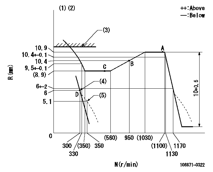
N:Pump speed
R:Rack position (mm)
(1)Variable speed specification.
(2)Tolerance for racks not indicated: +-0.05mm.
(3)Rack limit using stop lever: R1 (at N = N1)
(4)Main spring setting
(5)Damper spring setting
----------
R1=12.3+-0.1mm N1=0r/min
----------
----------
R1=12.3+-0.1mm N1=0r/min
----------
Speed control lever angle

F:Full speed
I:Idle
(1)Stopper bolt setting
----------
----------
a=6deg+-5deg b=19deg+-5deg
----------
----------
a=6deg+-5deg b=19deg+-5deg
0000000901
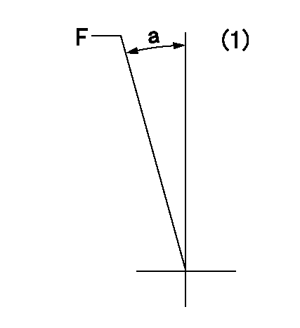
F:Full load
(1)Fix the lever at the full load position
----------
----------
a=5deg+-5deg
----------
----------
a=5deg+-5deg
Stop lever angle
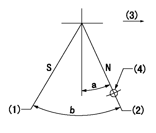
N:Pump normal
S:Stop the pump.
(1)Rack position = aa
(2)Rack position bb
(3)Drive side
(4)Use the hole above R = cc
----------
aa=1+0.5mm bb=12.3+-0.1mm cc=32mm
----------
a=6deg+-5deg b=31.5deg+-3deg
----------
aa=1+0.5mm bb=12.3+-0.1mm cc=32mm
----------
a=6deg+-5deg b=31.5deg+-3deg
Information:
1W4563, 1W5634 Gear Group
(1) Fuel pump drive gear.(2) Washer. Assemble with large diameter away from gear.(3) Bolt. With the timing pin and timing bolt correctly installed, put a clockwise force of 70 N m (50 lb ft) on the drive gear for the fuel pump and tighten bolt to ... 270 25 N m (200 20 lb ft)(4) Fuel pump idler gear. End play for the idler gear (new) ... 0.10 to 0.41 mm (.004 to .016 in)Maximum permissible end play (worn) ... 0.86 mm (.034 in)Bore in bearing for the idler gear (new) ... 35.004 0.048 mm (1.3781 .0019 in)Diameter of shaft for idler gear (new) ... 34.902 0.020 mm (1.3741 .0008 in)Clearance between shaft and bearing (new) ... 0.033 to 0.168 mm (.0013 to .0066 in)Maximum permissible clearance between shaft and bearing (worn) ... 0.23 mm (.009 in)(5) Plate. Assemble machined side of plate adjacent to the shaft.(6) Bolt. Tighten to ... 25 7 N m (18 5 lb ft)(7) Camshaft gear.(8) Bolts. Tighten to ... 55 7 N m (40 7 lb ft)(9) Crankshaft gear. Maximum temperature of the gear for installation on the crankshaft ... 316°C (600°F)(10) Idler gear for oil pump.(11) Drive gear for oil pump.2P9642 Gear Group
(1) Fuel pump drive gear.(2) Washer. Assemble with large diameter away from gear.(3) Bolt. With the timing pin and timing bolt correctly installed, put a clockwise force of 70 N m (50 lb ft) on the drive gear for the fuel pump and tighten bolt to ... 149 7 N m (110 5 lb ft)(4) Fuel pump idler gear. End play for the idler gear (new) ... 0.10 to 0.41 mm (.004 to .016 in)Maximum permissible end play (worn) ... 0.86 mm (.034 in)Bore in bearing for the idler gear (new) ... 35.004 0.048 mm (1.3781 .0019 in)Diameter of shaft for idler gear (new) ... 34.902 0.020 mm (1.3741 .0008 in)Clearance between shaft and bearing (new) ... 0.033 to 0.168 mm (.0013 to .0066 in)Maximum permissible clearance between shaft and bearing (worn) ... 0.23 mm (.009 in)(5) Plate. Assemble machined side of plate adjacent to the shaft.(6) Bolt. Tighten to ... 25 7 N m (18 5 lb ft)(7) Camshaft gear.(8) Bolts. Tighten to ... 55 7 N m (40 7 lb ft)(9) Crankshaft gear. Maximum temperature of the gear for installation on the crankshaft ... 316°C (600°F)(10) Idler gear for oil pump.(11) Drive gear for oil pump.
Have questions with 106871-0322?
Group cross 106871-0322 ZEXEL
Nissan-Diesel
Nissan-Diesel
Nissan-Diesel
106871-0322
9 400 618 018
1671397616
INJECTION-PUMP ASSEMBLY
RD8T
RD8T