Information injection-pump assembly
BOSCH
9 400 618 014
9400618014
ZEXEL
106871-0284
1068710284
NISSAN-DIESEL
1671397613
1671397613
Rating:
Service parts 106871-0284 INJECTION-PUMP ASSEMBLY:
1.
_
7.
COUPLING PLATE
8.
_
9.
_
11.
Nozzle and Holder
1660097019
12.
Open Pre:MPa(Kqf/cm2)
19.6(200)

15.
NOZZLE SET
Include in #1:
106871-0284
as INJECTION-PUMP ASSEMBLY
Cross reference number
BOSCH
9 400 618 014
9400618014
ZEXEL
106871-0284
1068710284
NISSAN-DIESEL
1671397613
1671397613
Zexel num
Bosch num
Firm num
Name
106871-0284
9 400 618 014
1671397613 NISSAN-DIESEL
INJECTION-PUMP ASSEMBLY
RE8 * K
RE8 * K
Calibration Data:
Adjustment conditions
Test oil
1404 Test oil ISO4113 or {SAEJ967d}
1404 Test oil ISO4113 or {SAEJ967d}
Test oil temperature
degC
40
40
45
Nozzle and nozzle holder
105780-8140
Bosch type code
EF8511/9A
Nozzle
105780-0000
Bosch type code
DN12SD12T
Nozzle holder
105780-2080
Bosch type code
EF8511/9
Opening pressure
MPa
17.2
Opening pressure
kgf/cm2
175
Injection pipe
Outer diameter - inner diameter - length (mm) mm 8-3-600
Outer diameter - inner diameter - length (mm) mm 8-3-600
Overflow valve opening pressure
kPa
157
123
191
Overflow valve opening pressure
kgf/cm2
1.6
1.25
1.95
Tester oil delivery pressure
kPa
157
157
157
Tester oil delivery pressure
kgf/cm2
1.6
1.6
1.6
Direction of rotation (viewed from drive side)
Right R
Right R
Injection timing adjustment
Direction of rotation (viewed from drive side)
Right R
Right R
Injection order
1-8-7-5-
4-3-6-2
Pre-stroke
mm
3.65
3.6
3.7
Beginning of injection position
Governor side NO.1
Governor side NO.1
Difference between angles 1
Cal 1-8 deg. 45 44.5 45.5
Cal 1-8 deg. 45 44.5 45.5
Difference between angles 2
Cal 1-7 deg. 90 89.5 90.5
Cal 1-7 deg. 90 89.5 90.5
Difference between angles 3
Cal 1-5 deg. 135 134.5 135.5
Cal 1-5 deg. 135 134.5 135.5
Difference between angles 4
Cal 1-4 deg. 180 179.5 180.5
Cal 1-4 deg. 180 179.5 180.5
Difference between angles 5
Cal 1-3 deg. 225 224.5 225.5
Cal 1-3 deg. 225 224.5 225.5
Difference between angles 6
Cal 1-6 deg. 270 269.5 270.5
Cal 1-6 deg. 270 269.5 270.5
Difference between angles 7
Cyl.1-2 deg. 315 314.5 315.5
Cyl.1-2 deg. 315 314.5 315.5
Injection quantity adjustment
Adjusting point
A
Rack position
10
Pump speed
r/min
700
700
700
Average injection quantity
mm3/st.
105.7
104.7
106.7
Max. variation between cylinders
%
0
-4
4
Basic
*
Fixing the lever
*
Injection quantity adjustment_02
Adjusting point
B
Rack position
8.9+-0.5
Pump speed
r/min
1250
1250
1250
Average injection quantity
mm3/st.
96.1
94.1
98.1
Max. variation between cylinders
%
0
-4
4
Fixing the lever
*
Injection quantity adjustment_03
Adjusting point
C
Rack position
6.3+-0.5
Pump speed
r/min
250
250
250
Average injection quantity
mm3/st.
12.9
10.9
14.9
Max. variation between cylinders
%
0
-10
10
Fixing the rack
*
Timer adjustment
Pump speed
r/min
750
Advance angle
deg.
0.5
Timer adjustment_02
Pump speed
r/min
900
Advance angle
deg.
1.4
0.9
1.9
Timer adjustment_03
Pump speed
r/min
1150
Advance angle
deg.
5.5
5
6
Remarks
Finish
Finish
Test data Ex:
Governor adjustment
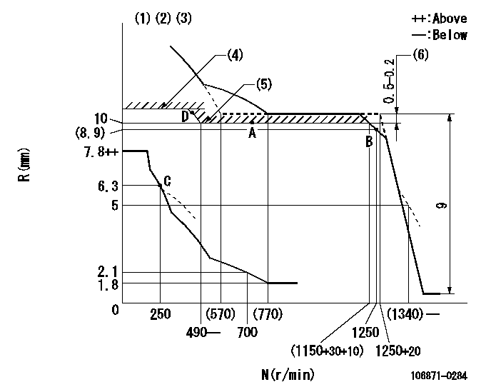
N:Pump speed
R:Rack position (mm)
(1)Lever ratio: RT
(2)Target shim dimension: TH
(3)Damper spring setting: DL
(4)Rack limit using stop lever: R1 (at N = N1)
(5)Excess fuel setting for starting
(6)Rack difference to N = N2
----------
RT=1 TH=1.8mm DL=6.3-0.2mm R1=11+0.2mm N1=100--r/min N2=1100r/min
----------
----------
RT=1 TH=1.8mm DL=6.3-0.2mm R1=11+0.2mm N1=100--r/min N2=1100r/min
----------
Speed control lever angle

F:Full speed
----------
----------
a=(13deg)+-5deg
----------
----------
a=(13deg)+-5deg
0000000901

F:Full load
I:Idle
(1)Stopper bolt setting
----------
----------
a=24.5deg+-5deg b=31deg+-3deg
----------
----------
a=24.5deg+-5deg b=31deg+-3deg
Stop lever angle
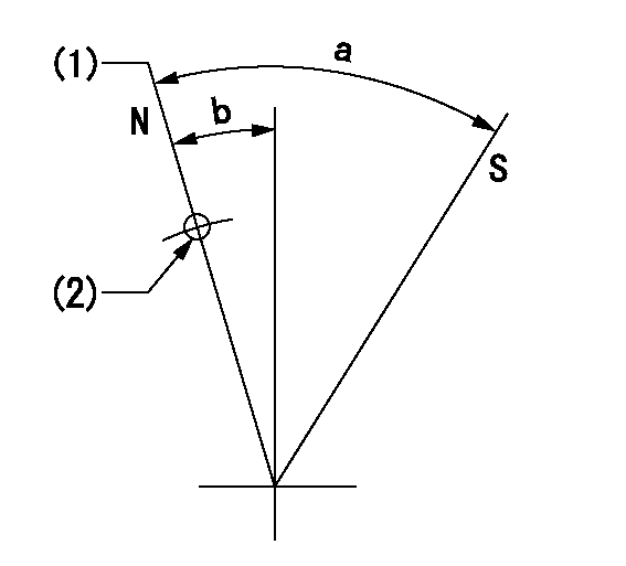
N:Pump normal
S:Stop the pump.
(1)Rack position = aa
(2)Use the hole at R = bb
----------
aa=11+0.2mm bb=32mm
----------
a=28.5deg+-5deg b=3deg+-5deg
----------
aa=11+0.2mm bb=32mm
----------
a=28.5deg+-5deg b=3deg+-5deg
Timing setting

(1)Pump vertical direction
(2)Position of the coupling's key groove at the beginning of injection of the No. 8 cylinder.
(3)-
(4)-
----------
----------
a=(90deg)
----------
----------
a=(90deg)
Information:
Alternator (Bosch)
The alternator is driven by V-belts from the crankshaft pulley. This alternator is a three phase, self-rectifying charging unit. The regulator is part of the alternator.
Bosch Alternator
(1) Fan. (2) Stator winding. (3) Field winding. (4) Regulator. (5) Ball bearing. (6) Roller bearing. (7) Rotor. (8) Rectifier assembly.This alternator design has no need for slip rings or brushes, and the only part that has movement is the rotor assembly. All conductors that carry current are stationary. The conductors are: the field winding, stator windings, six rectifying diodes, and the regulator circuit components.The rotor assembly has many magnetic poles like fingers with air space between each opposite pole. The poles have residual magnetism (like permanent magnets) that produce a small amount of magnet-like lines of force (magnetic field) between the poles. As the rotor assembly begins to turn between the field winding and the stator windings, a small amount of alternating current (AC) is produced in the stator windings from the small magnetic lines of force made by the residual magnetism of the poles. This AC current is changed to direct current (DC) when it passes through the diodes of the rectifier bridge. Most of this current goes to charge the battery and to supply the low amperage circuit, and the remainder is sent to the field windings. The DC current flow through the field windings (wires around an iron core) now increases the strength of the magnetic lines of force. These stronger lines of force now increase the amount of AC current produced in the stator windings. The increased speed of the rotor assembly also increases the current and voltage output of the alternator.The voltage regulator is a solid state (transistor, stationary parts) electronic switch. It feels the voltage in the system and switches on and off many times a second to control the field current (DC current to the field windings) for the alternator to make the needed voltage output.Alternator (Nippondenso)
The alternator is driven by V-belts from the crankshaft pulley. The Nippondenso alternator has three-phase, full-wave rectified output. It is brushless. The rotor and bearings are the only moving parts. The regulator is part of the alternator.
Nippondenso Alternator
(1) Fan. (2) Front frame assembly. (3) Stator assembly. (4) Rotor assembly. (5) Field winding (coil assembly). (6) Regulator assembly. (7) Condenser (suppression capacitor). (8) Rectifier assembly. (9) Rear frame assembly.When the engine is started and the rotor turns inside the stator windings, three-phase alternating current (AC) and rapidly rising voltage is generated.A small amount of alternating current (AC) is changed (rectified) to pulsating direct current (DC) by the exciter diodes on the rectifier assembly. Output current from these diodes adds to the initial current which flows through the rotor field windings from residual magnetism. This will make the rotor a stronger magnet and cause the alternator to become activated automatically. As rotor speed, current and voltages increase, the rotor field current increases enough until the alternator becomes fully activated.The main battery charging current is charged (rectified) from AC to
Have questions with 106871-0284?
Group cross 106871-0284 ZEXEL
Nissan-Diesel
Nissan-Diesel
Nissan-Diesel
Nissan-Diesel
Nissan-Diesel
Nissan-Diesel
Nissan-Diesel
Nissan-Diesel
106871-0284
9 400 618 014
1671397613
INJECTION-PUMP ASSEMBLY
RE8
RE8