Information injection-pump assembly
ZEXEL
106871-0171
1068710171

Rating:
Service parts 106871-0171 INJECTION-PUMP ASSEMBLY:
1.
_
6.
COUPLING PLATE
7.
COUPLING PLATE
8.
_
9.
_
11.
Nozzle and Holder
16600-97005
12.
Open Pre:MPa(Kqf/cm2)
22.6{230}
15.
NOZZLE SET
Include in #1:
106871-0171
as INJECTION-PUMP ASSEMBLY
Cross reference number
ZEXEL
106871-0171
1068710171
Zexel num
Bosch num
Firm num
Name
106871-0171
INJECTION-PUMP ASSEMBLY
Calibration Data:
Adjustment conditions
Test oil
1404 Test oil ISO4113 or {SAEJ967d}
1404 Test oil ISO4113 or {SAEJ967d}
Test oil temperature
degC
40
40
45
Nozzle and nozzle holder
105780-8140
Bosch type code
EF8511/9A
Nozzle
105780-0000
Bosch type code
DN12SD12T
Nozzle holder
105780-2080
Bosch type code
EF8511/9
Opening pressure
MPa
17.2
Opening pressure
kgf/cm2
175
Injection pipe
Outer diameter - inner diameter - length (mm) mm 8-3-600
Outer diameter - inner diameter - length (mm) mm 8-3-600
Overflow valve opening pressure
kPa
157
123
191
Overflow valve opening pressure
kgf/cm2
1.6
1.25
1.95
Tester oil delivery pressure
kPa
157
157
157
Tester oil delivery pressure
kgf/cm2
1.6
1.6
1.6
Direction of rotation (viewed from drive side)
Right R
Right R
Injection timing adjustment
Direction of rotation (viewed from drive side)
Right R
Right R
Injection order
1-8-7-5-
4-3-6-2
Pre-stroke
mm
3.65
3.6
3.7
Beginning of injection position
Governor side NO.1
Governor side NO.1
Difference between angles 1
Cal 1-8 deg. 45 44.5 45.5
Cal 1-8 deg. 45 44.5 45.5
Difference between angles 2
Cal 1-7 deg. 90 89.5 90.5
Cal 1-7 deg. 90 89.5 90.5
Difference between angles 3
Cal 1-5 deg. 135 134.5 135.5
Cal 1-5 deg. 135 134.5 135.5
Difference between angles 4
Cal 1-4 deg. 180 179.5 180.5
Cal 1-4 deg. 180 179.5 180.5
Difference between angles 5
Cal 1-3 deg. 225 224.5 225.5
Cal 1-3 deg. 225 224.5 225.5
Difference between angles 6
Cal 1-6 deg. 270 269.5 270.5
Cal 1-6 deg. 270 269.5 270.5
Difference between angles 7
Cyl.1-2 deg. 315 314.5 315.5
Cyl.1-2 deg. 315 314.5 315.5
Injection quantity adjustment
Adjusting point
A
Rack position
11.3
Pump speed
r/min
750
750
750
Average injection quantity
mm3/st.
139.2
138.2
140.2
Max. variation between cylinders
%
0
-2.5
2.5
Basic
*
Fixing the lever
*
Boost pressure
kPa
40
40
Boost pressure
mmHg
300
300
Injection quantity adjustment_02
Adjusting point
B
Rack position
9.9
Pump speed
r/min
500
500
500
Average injection quantity
mm3/st.
109.1
107.1
111.1
Max. variation between cylinders
%
0
-4
4
Fixing the lever
*
Boost pressure
kPa
0
0
0
Boost pressure
mmHg
0
0
0
Injection quantity adjustment_03
Adjusting point
C
Rack position
6+-0.5
Pump speed
r/min
300
300
300
Average injection quantity
mm3/st.
12.8
11.7
13.9
Max. variation between cylinders
%
0
-15
15
Fixing the rack
*
Boost pressure
kPa
0
0
0
Boost pressure
mmHg
0
0
0
Boost compensator adjustment
Pump speed
r/min
500
500
500
Rack position
9.9
Boost pressure
kPa
16
9.3
22.7
Boost pressure
mmHg
120
70
170
Boost compensator adjustment_02
Pump speed
r/min
500
500
500
Rack position
11.3
Boost pressure
kPa
30
28.7
31.3
Boost pressure
mmHg
225
215
235
Timer adjustment
Pump speed
r/min
300+100
Advance angle
deg.
0
0
0
Remarks
Start
Start
Timer adjustment_02
Pump speed
r/min
600
Advance angle
deg.
1.7
1.2
2.2
Timer adjustment_03
Pump speed
r/min
900
Advance angle
deg.
3.4
2.9
3.9
Timer adjustment_04
Pump speed
r/min
1250+50
Advance angle
deg.
5.5
5
6
Remarks
Finish
Finish
Test data Ex:
Governor adjustment

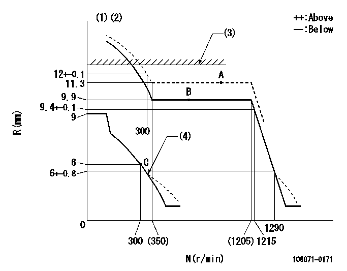
N:Pump speed
R:Rack position (mm)
(1)Target notch: K
(2)Tolerance for racks not indicated: +-0.05mm.
(3)RACK LIMIT: RAL
(4)Damper spring setting: DL
----------
K=17 RAL=12.3+-0.1mm DL=6-0.2mm
----------
----------
K=17 RAL=12.3+-0.1mm DL=6-0.2mm
----------
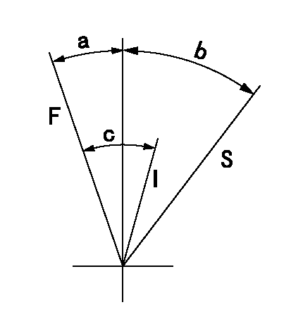
Speed control lever angle

F:Full speed
I:Idle
S:Stop
----------
----------
a=18deg+-5deg b=32deg+-3deg c=29deg+-5deg
----------
----------
a=18deg+-5deg b=32deg+-3deg c=29deg+-5deg
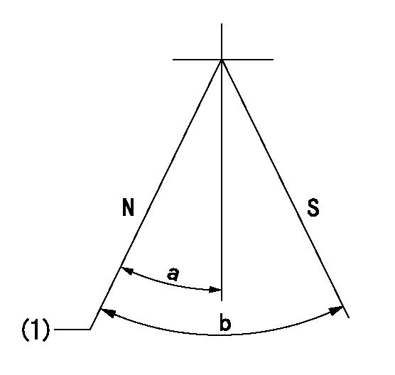
Stop lever angle

N:Pump normal
S:Stop the pump.
(1)Normal
----------
----------
a=16.5deg+-5deg b=50deg+-5deg
----------
----------
a=16.5deg+-5deg b=50deg+-5deg
0000001501 GOV FULL LOAD ADJUSTMENT

Title1:Full load stopper adjustment
Title2:Governor set speed
LABEL1:Distinguishing
LABEL2:Pump speed (r/min)
LABEL3:Ave. injection quantity (mm3/st)
LABEL4:Max. var. bet. cyl.
LABEL5:Remarks
LABEL6:Distinguishing
LABEL7:Governor set speed (r/min)
LABEL8:Maximum no-load speed (r/min)
LABEL9:Remarks
(1)Adjustment conditions are the same as those for measuring injection quantity.
(2)At high idle rack position L
----------
L=6mm
----------
a1=A a2=B a3=C a4=D r1=700r/min r2=750r/min r3=700r/min r4=700r/min Q1=- Q2=139.2+-1mm3/st Q3=- Q4=102.6+-1mm3/st c1=+-2.5% c2=+-2.5% c3=+-2.5% c4=+-2.5% a5=24 a6=23 a7=22 a8=21 a9=20 a10=19 a11=18 a12=17 a13=- a14=- a15=- r5=1200r/min r6=1150r/min r7=1100r/min r8=1050r/min r9=1000r/min r10=950r/min r11=900r/min r12=850r/min r13=- r14=- r15=- R5=1290+-30r/min R6=1235+-28r/min R7=1180+-27r/min R8=1130+-26r/min R9=1075+-25r/min R10=1020+-23r/min R11=965+-22r/min R12=915+-22r/min R13=- R14=- R15=-
----------
L=6mm
----------
a1=A a2=B a3=C a4=D r1=700r/min r2=750r/min r3=700r/min r4=700r/min Q1=- Q2=139.2+-1mm3/st Q3=- Q4=102.6+-1mm3/st c1=+-2.5% c2=+-2.5% c3=+-2.5% c4=+-2.5% a5=24 a6=23 a7=22 a8=21 a9=20 a10=19 a11=18 a12=17 a13=- a14=- a15=- r5=1200r/min r6=1150r/min r7=1100r/min r8=1050r/min r9=1000r/min r10=950r/min r11=900r/min r12=850r/min r13=- r14=- r15=- R5=1290+-30r/min R6=1235+-28r/min R7=1180+-27r/min R8=1130+-26r/min R9=1075+-25r/min R10=1020+-23r/min R11=965+-22r/min R12=915+-22r/min R13=- R14=- R15=-
Information:
307-OR to S Terminal of Key Switch, 308-YL to R Terminal of Key Switch, 105-BR to B Terminal of Key Switch,7. Connect additional leads to the key switch by loosening the screws and placing 307-OR, 308-YL and 105-BR leads under the screws and tighten. Make sure to match existing wire codes and color.8. Clip EPTC-II data link extension of EUI Retro harness (used for EPTC II) with 3T3048 clip assembly. 9. Remove existing console panel located towards rear of console directly above transmission control box (EPTC).
1053652 Panel Group. 1. 1052038 Plate. 2. 1052484 Film. 3. 6T6066 Switch Assembly. 4. Two 6T6329 Bezel. 5. Four 5P7590 Bolt. 6. 6T3990 Switch Assembly. 7. Four 3E8043 Screw. 8. 8C6354 Cap. 9. Four 5P1075 Washer. 10. 7T0493 Plug. 11. Four 6V8801 Nut. 12. Two 3T0304 Base. 13. Two 7N1996 Lamp. 14. Two 6T7058 Lens. 15. Two 6T2774 Clip. 16. Four 6B4540 Nut. 17. Four 6D3033 Screw. 18. Four 6V9497 Washer. 19. 1049543 Harness Assembly. 20. 1052045 Panel. 1 10. Assemble the 1053652 Panel Group as shown in the illustrations above.
1049543 Harness Assembly11. Connect the harness and individual wires as shown. Clip 1049543 Harness to the panel with 8M2773 Clip.12. Connect the EUI Retro harness to 1049543 Harness Assembly. Clip the connection with a 3T3046 Clip Assembly. Position the panel group back in place on the console with the existing hardware.Cab EUI Retrofit Harness (Front of Cab)
A major portion of the EUI Retro harness will extend through the tunnel to the front of the cab where connections must be made to the:* Overspeed warning light* Throttle pedal* Warning hornOverspeed warning light
Route the front portion of the Retro Harness through the tunnel under the cab. The plate under the cab may be removed for easier access.All trucks after 9ZC133 were equipped with an engine overspeed control module located in the front of the cab. This function is now handled by the EUI-Electronic Control Module. Part of this old system (8W0584 Wiring Group-Cab) must be disconnected and removed.Remove the following items.
8W0584 Wiring Group. 1. 8W7193 Harness Assembly. 2. 7T3821 Control Group. 3. 9D3721 Switch. 4. Two 7N8419 Terminals. 5. Three 4M5282 Bolts. 6. Three 5P4115 Washers.Overspeed Warning Group
All trucks with PINS 9ZC1 thru 9ZC132, a Special Instruction SEHS8863 Installation of Off-Highway Truck Engine Overspeed Warning Indicator Group was available to update these trucks with the stand alone engine overspeed system.This Special Instruction should be used for all trucks within this PIN range.* Trucks that was not retro-fitted with engine overspeed.* Trucks that had been retro-fitted with Special Instruction SEHS8863.Trucks That Was Not Retro-fitted
Install just the items given in the following chart on these trucks. The 12 items in the chart above must be installed to complete the EUI Retro-fit on those trucks that had no overspeed warning installed. The following Steps were taken from Special Instruction SEHS8863. The following Steps are similar to the Steps in SEHS8863. Do only those things that are spelled out in these 12 Steps, which were taken from SEHS8863.1. Disconnect
Have questions with 106871-0171?
Group cross 106871-0171 ZEXEL
Nissan-Diesel
Nissan-Diesel
Nissan-Diesel
Nissan-Diesel
Nissan-Diesel
Nissan-Diesel
106871-0171
INJECTION-PUMP ASSEMBLY