Information injection-pump assembly
ZEXEL
106871-0020
1068710020

Rating:
Cross reference number
ZEXEL
106871-0020
1068710020
Zexel num
Bosch num
Firm num
Name
106871-0020
INJECTION-PUMP ASSEMBLY
Calibration Data:
Adjustment conditions
Test oil
1404 Test oil ISO4113 or {SAEJ967d}
1404 Test oil ISO4113 or {SAEJ967d}
Test oil temperature
degC
40
40
45
Nozzle
105015-3510
Nozzle holder
105031-4210
Opening pressure
MPa
22.6
Opening pressure
kgf/cm2
230
Injection pipe
Outer diameter - inner diameter - length (mm) mm 6-2-1010
Outer diameter - inner diameter - length (mm) mm 6-2-1010
Overflow valve
132424-0620
Overflow valve opening pressure
kPa
157
123
191
Overflow valve opening pressure
kgf/cm2
1.6
1.25
1.95
Tester oil delivery pressure
kPa
157
157
157
Tester oil delivery pressure
kgf/cm2
1.6
1.6
1.6
Direction of rotation (viewed from drive side)
Right R
Right R
Injection timing adjustment
Direction of rotation (viewed from drive side)
Right R
Right R
Injection order
1-8-7-5-
4-3-6-2
Pre-stroke
mm
3.65
3.6
3.7
Beginning of injection position
Governor side NO.1
Governor side NO.1
Difference between angles 1
Cal 1-8 deg. 45 44.5 45.5
Cal 1-8 deg. 45 44.5 45.5
Difference between angles 2
Cal 1-7 deg. 90 89.5 90.5
Cal 1-7 deg. 90 89.5 90.5
Difference between angles 3
Cal 1-5 deg. 135 134.5 135.5
Cal 1-5 deg. 135 134.5 135.5
Difference between angles 4
Cal 1-4 deg. 180 179.5 180.5
Cal 1-4 deg. 180 179.5 180.5
Difference between angles 5
Cal 1-3 deg. 225 224.5 225.5
Cal 1-3 deg. 225 224.5 225.5
Difference between angles 6
Cal 1-6 deg. 270 269.5 270.5
Cal 1-6 deg. 270 269.5 270.5
Difference between angles 7
Cyl.1-2 deg. 315 314.5 315.5
Cyl.1-2 deg. 315 314.5 315.5
Injection quantity adjustment
Adjusting point
A
Rack position
11.7
Pump speed
r/min
1200
1200
1200
Average injection quantity
mm3/st.
128.5
126.5
130.5
Max. variation between cylinders
%
0
-4
4
Fixing the lever
*
Boost pressure
kPa
40
40
Boost pressure
mmHg
300
300
Injection quantity adjustment_02
Adjusting point
B
Rack position
11.7
Pump speed
r/min
750
750
750
Average injection quantity
mm3/st.
139
137
141
Max. variation between cylinders
%
0
-4
4
Basic
*
Fixing the lever
*
Boost pressure
kPa
40
40
Boost pressure
mmHg
300
300
Injection quantity adjustment_03
Adjusting point
C
Rack position
10.5
Pump speed
r/min
400
400
400
Average injection quantity
mm3/st.
105
103
107
Max. variation between cylinders
%
0
-4
4
Fixing the lever
*
Boost pressure
kPa
0
0
0
Boost pressure
mmHg
0
0
0
Injection quantity adjustment_04
Adjusting point
D
Rack position
7.6+-0.5
Pump speed
r/min
200
200
200
Average injection quantity
mm3/st.
20
18
22
Max. variation between cylinders
%
0
-10
10
Fixing the rack
*
Boost compensator adjustment
Pump speed
r/min
400
400
400
Rack position
10.5
Boost pressure
kPa
11.3
4.6
18
Boost pressure
mmHg
85
35
135
Boost compensator adjustment_02
Pump speed
r/min
400
400
400
Rack position
11.7
Boost pressure
kPa
34.7
33.4
36
Boost pressure
mmHg
260
250
270
Timer adjustment
Pump speed
r/min
300-100
Advance angle
deg.
0
0
0
Remarks
Start
Start
Timer adjustment_02
Pump speed
r/min
600
Advance angle
deg.
0.7
0.2
1.2
Timer adjustment_03
Pump speed
r/min
900
Advance angle
deg.
1.6
1.1
2.1
Timer adjustment_04
Pump speed
r/min
1250-50
Advance angle
deg.
3
2.5
3.5
Remarks
Finish
Finish
Test data Ex:
Governor adjustment
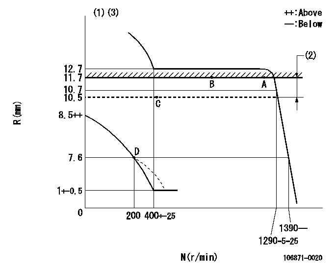
N:Pump speed
R:Rack position (mm)
(1)Beginning of damper spring operation: DL
(2)RACK LIMIT
(3)Boost compensator stroke
----------
DL=7.1-0.2mm
----------
----------
DL=7.1-0.2mm
----------
0000000901
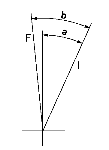
F:Full load
I:Idle
----------
----------
a=19deg+-3deg b=20deg+-5deg
----------
----------
a=19deg+-3deg b=20deg+-5deg
Stop lever angle
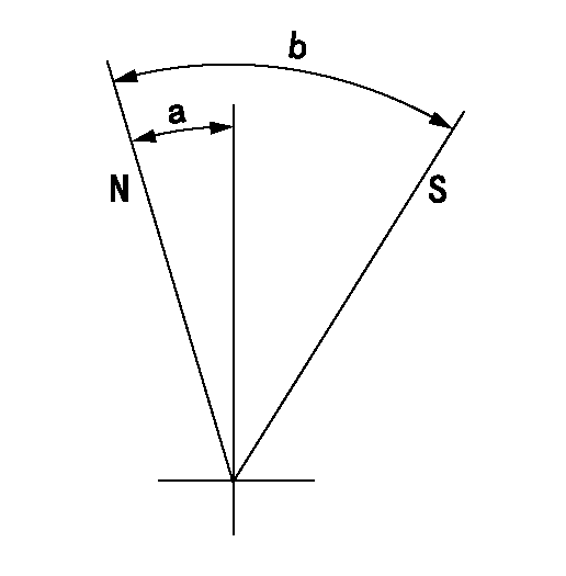
N:Pump normal
S:Stop the pump.
----------
----------
a=11deg+-5deg b=36deg+-3deg
----------
----------
a=11deg+-5deg b=36deg+-3deg
Information:
Adjust - to conform and correspond to specifications. Check - to observe for satisfactory conditions, accuracy, safety or performance. Exchange - to trade a worn or failing component for a remanufactured or rebuilt component. Inspect - to examine closely, in critical appraisal, while testing or evaluating components or systems. Inspect/Rebuild or Exchange - to examine closely, then making the decision on repair option (i.e. Rebuild or Exchange). Lubricate - to apply a lubricant (oil, grease, etc.) as specified for reducing friction, heat and wear between solid surfaces. Protective Devices - indicators such as gauges, lights, emergency shutoffs, etc., that alert an operator that a potential problem may exist. Failure to respond to these indicators in a timely manner could result in serious engine damage. Rebuild - to repair worn or failing component with new parts, components and/or remanufactured components. Replace - to install something new, remanufactured or rebuilt in place of an existing worn or failing component. Service Hours (Electrical) - records the time (clock hours) the engine is actually running but does not reflect variations in speed, load, etc. Some engines are equipped with mechanical service meters reading in Service Meter Units (SMU). The Maintenance Schedules are developed for clock hours or fuel consumption. For most users, clock hours are the standard interval for maintenance and SMU's can be roughly equal to clock hours. However, Caterpillar recommends that fuel consumption be used as the preferred method of determining intervals rather than SMU's or clock hours.Interval Categories
Engine components can generally be grouped into speed sensitive and load sensitive categories. The maintenance interval for each item listed in the Maintenance Schedule is based on either engine speed or load. Speed sensitive items such as water pumps an air compressors are not primarily affected by the operating load on your engine. The load on an engine will not significantly accelerate the repair or replacement cycle for speed sensitive items. The maintenance intervals established for speed sensitive items are based on service hours. Load sensitive items such as piston rings and cylinder liners are affected by the operating load on your engine. Generally speaking, the lower the load, the longer the engine life. Conversely, the higher the load, the shorter the engine life. A heavy load on an engine will accelerate the repair or replacement cycle for load sensitive items.Load sensitive items are normally internal engine components. The amount of fuel consumed is directly related to the load on your engine.The maintenance interval for load sensitive items includes fuel consumption, since the amount of fuel consumed is directly related to the load on your engine.Caterpillar recommends performing maintenance on load sensitive items at maintenance intervals based on the quantity of fuel consumed.
Engine components can generally be grouped into speed sensitive and load sensitive categories. The maintenance interval for each item listed in the Maintenance Schedule is based on either engine speed or load. Speed sensitive items such as water pumps an air compressors are not primarily affected by the operating load on your engine. The load on an engine will not significantly accelerate the repair or replacement cycle for speed sensitive items. The maintenance intervals established for speed sensitive items are based on service hours. Load sensitive items such as piston rings and cylinder liners are affected by the operating load on your engine. Generally speaking, the lower the load, the longer the engine life. Conversely, the higher the load, the shorter the engine life. A heavy load on an engine will accelerate the repair or replacement cycle for load sensitive items.Load sensitive items are normally internal engine components. The amount of fuel consumed is directly related to the load on your engine.The maintenance interval for load sensitive items includes fuel consumption, since the amount of fuel consumed is directly related to the load on your engine.Caterpillar recommends performing maintenance on load sensitive items at maintenance intervals based on the quantity of fuel consumed.
Have questions with 106871-0020?
Group cross 106871-0020 ZEXEL
Nissan-Diesel
106871-0020
INJECTION-PUMP ASSEMBLY