Information injection-pump assembly
ZEXEL
106871-0000
1068710000

Rating:
Cross reference number
ZEXEL
106871-0000
1068710000
Zexel num
Bosch num
Firm num
Name
106871-0000
INJECTION-PUMP ASSEMBLY
Calibration Data:
Adjustment conditions
Test oil
1404 Test oil ISO4113 or {SAEJ967d}
1404 Test oil ISO4113 or {SAEJ967d}
Test oil temperature
degC
40
40
45
Nozzle and nozzle holder
105101-4760
Nozzle
105015-3440
Bosch type code
DLLA142S394NP66
Nozzle holder
105031-4210
Opening pressure
MPa
22.6
Opening pressure
kgf/cm2
230
Injection pipe
Outer diameter - inner diameter - length (mm) mm 6-2.2-1010
Outer diameter - inner diameter - length (mm) mm 6-2.2-1010
Overflow valve
132424-0620
Overflow valve opening pressure
kPa
157
123
191
Overflow valve opening pressure
kgf/cm2
1.6
1.26
1.94
Tester oil delivery pressure
kPa
157
157
157
Tester oil delivery pressure
kgf/cm2
1.6
1.6
1.6
Direction of rotation (viewed from drive side)
Right R
Right R
Injection timing adjustment
Direction of rotation (viewed from drive side)
Right R
Right R
Injection order
1-8-7-5-
4-3-6-2
Pre-stroke
mm
3.65
3.6
3.7
Beginning of injection position
Governor side NO.1
Governor side NO.1
Difference between angles 1
Cal 1-8 deg. 45 44.5 45.5
Cal 1-8 deg. 45 44.5 45.5
Difference between angles 2
Cal 1-7 deg. 90 89.5 90.5
Cal 1-7 deg. 90 89.5 90.5
Difference between angles 3
Cal 1-5 deg. 135 134.5 135.5
Cal 1-5 deg. 135 134.5 135.5
Difference between angles 4
Cal 1-4 deg. 180 179.5 180.5
Cal 1-4 deg. 180 179.5 180.5
Difference between angles 5
Cal 1-3 deg. 225 224.5 225.5
Cal 1-3 deg. 225 224.5 225.5
Difference between angles 6
Cal 1-6 deg. 270 269.5 270.5
Cal 1-6 deg. 270 269.5 270.5
Difference between angles 7
Cyl.1-2 deg. 315 314.5 315.5
Cyl.1-2 deg. 315 314.5 315.5
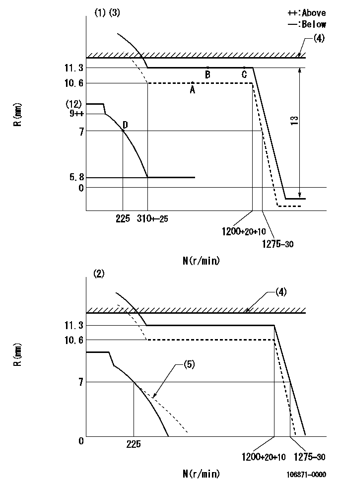
Injection quantity adjustment
Adjusting point
A
Rack position
10.6
Pump speed
r/min
500
500
500
Average injection quantity
mm3/st.
116
114
118
Max. variation between cylinders
%
0
-4
4
Fixing the lever
*
Boost pressure
kPa
0
0
0
Boost pressure
mmHg
0
0
0
Injection quantity adjustment_02
Adjusting point
B
Rack position
11.3
Pump speed
r/min
750
750
750
Average injection quantity
mm3/st.
135
133
137
Max. variation between cylinders
%
0
-4
4
Basic
*
Fixing the lever
*
Boost pressure
kPa
40
40
Boost pressure
mmHg
300
300
Injection quantity adjustment_03
Adjusting point
C
Rack position
11.3
Pump speed
r/min
1200
1200
1200
Average injection quantity
mm3/st.
123
120
126
Max. variation between cylinders
%
0
-4
4
Fixing the lever
*
Boost pressure
kPa
40
40
Boost pressure
mmHg
300
300
Injection quantity adjustment_04
Adjusting point
D
Rack position
7+-0.5
Pump speed
r/min
225
225
225
Average injection quantity
mm3/st.
20
18
22
Max. variation between cylinders
%
0
-10
10
Fixing the rack
*
Boost compensator adjustment
Pump speed
r/min
500
500
500
Rack position
10.6
Boost pressure
kPa
16
9.3
22.7
Boost pressure
mmHg
120
70
170
Boost compensator adjustment_02
Pump speed
r/min
500
500
500
Rack position
11.3
Boost pressure
kPa
30
28.7
31.3
Boost pressure
mmHg
225
215
235
Timer adjustment
Pump speed
r/min
300+-50
Advance angle
deg.
0
0
0
Remarks
Start
Start
Timer adjustment_02
Pump speed
r/min
600
Advance angle
deg.
1.7
1.2
2.2
Timer adjustment_03
Pump speed
r/min
900
Advance angle
deg.
3.4
2.9
3.9
Timer adjustment_04
Pump speed
r/min
1250+50
Advance angle
deg.
5.5
5
6
Remarks
Finish
Finish
Test data Ex:
Governor adjustment
N:Pump speed
R:Rack position (mm)
(1)Speed control lever full position
(2)Load control lever's full position
(3)Target notch: K
(4)RACK LIMIT: RAL
(5)Damper spring setting: DL
----------
K=5 RAL=11.7+-0.1mm DL=7-0.2mm
----------
----------
K=5 RAL=11.7+-0.1mm DL=7-0.2mm
----------
Speed control lever angle
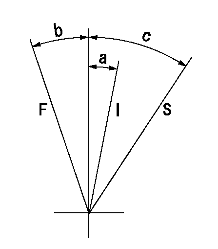
F:Full speed
I:Idle
S:Stop
----------
----------
a=21deg+-5deg b=10.5deg+-5deg c=32deg+-3deg
----------
----------
a=21deg+-5deg b=10.5deg+-5deg c=32deg+-3deg
0000000901
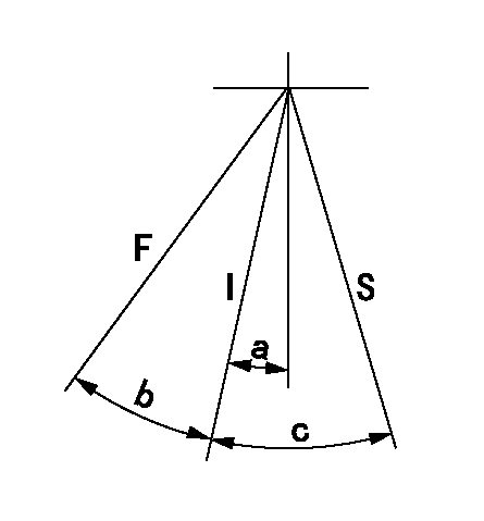
F:Full load
I:Idle
S:Stop
----------
----------
a=5deg+-5deg b=12deg+-3deg c=13.5deg+-3deg
----------
----------
a=5deg+-5deg b=12deg+-3deg c=13.5deg+-3deg
Information:
Stopping the engine immediately after it has been working under load can result in overheating and accelerated wear of the engine components. Allow the engine to cool down before stopping. Avoiding hot engine shutdowns will maximize turbocharger shaft and bearing life.
Emergency Stopping
Emergency shutoff controls are for EMERGENCY use ONLY. DO NOT use Emergency shutoff devices or controls for normal stopping procedure.
Make sure that any external system components that have been operating to support engine operation are secured after any stop.Emergency Stop Buttons
Emergency Stop Button, shown mounted on a junction box.Emergency stops may be made by pushing the Emergency Stop Button located on the junction box (if equipped). Both the Button and the air inlet shutoff (if equipped) require resetting before the engine will start.
Control Panel Emergency Stop Button.If equipped with the EMCPII Control Panel, press the Emergency Stop Button for an emergency stop. The ECS must be reset before resuming operation. Move the ECS to the OFF/RESET position. The ECS can also be used to shut the engine off in an emergency. Move the ECS to the OFF/RESET position. The engine will immediately shut off.Manual Stopping
A manual shutoff shaft is provided to override the governor control. The shaft will move the fuel control linkage to the FUEL OFF position. Refer to the Model Views for the engine location of the shaft. The engine may be stopped by using the shaft and the Woodward Actuator (if equipped) or the Mechanical Governor (if equipped).
Typical Woodward Actuator Control Lever.If equipped with a Woodward Actuator, move the control lever to the FUEL OFF position.
Typical Mechanical Governor ControlIf equipped with a Mechanical Governor Control, move the control to the FUEL OFF position.Hold the lever at the FUEL OFF position until the engine stops.Air Shutoff (If Equipped)
Some engines are equipped with an air shutoff, located between the aftercooler and the turbocharger. If equipped with an air shutoff lever, move the lever to the OFF position.Manual Stop Procedure
There may be several ways to shut off your engine. Make sure the shutoff procedures are understood. Use the following general guidelines for stopping the engine.EPG Engines
If the ECS is in the AUTO position and the remote contact opens, the engine will run for a pre-programmed cool down period. This will only occur when the cool down mode is used. If the cool down mode is not used, the engine will shut off immediately.
If the ECS is in the AUTO position, the remote contact opens, and the cool down time expires, the CTR will be unlatched and the starting motors may be re-engaged.1. Open the main electrical circuit breaker to remove the load.2. The engine should be run for a cool down period before being shut off. This can be accomplished with the COOLDOWN STOP switch, or the operator can control the cool down and shut off.
To use the COOLDOWN/STOP switch, turn the ECS to the COOLDOWN/STOP position. The engine will operate for a pre-programmed time period. The timer will active the fuel shutoff after the cool down.Alternatively,
Have questions with 106871-0000?
Group cross 106871-0000 ZEXEL
106871-0000
INJECTION-PUMP ASSEMBLY