Information injection-pump assembly
BOSCH
F 019 Z10 232
f019z10232
ZEXEL
106861-2660
1068612660
MITSUBISHI
ME442876
me442876

Rating:
Service parts 106861-2660 INJECTION-PUMP ASSEMBLY:
1.
_
7.
COUPLING PLATE
8.
_
9.
_
11.
Nozzle and Holder
12.
Open Pre:MPa(Kqf/cm2)
21.6(220)
15.
NOZZLE SET
Include in #1:
106861-2660
as INJECTION-PUMP ASSEMBLY
Cross reference number
BOSCH
F 019 Z10 232
f019z10232
ZEXEL
106861-2660
1068612660
MITSUBISHI
ME442876
me442876
Zexel num
Bosch num
Firm num
Name
106861-2660
F 019 Z10 232
ME442876 MITSUBISHI
INJECTION-PUMP ASSEMBLY
8DC9TL K 14CD INJECTION PUMP ASSY PE8P PE
8DC9TL K 14CD INJECTION PUMP ASSY PE8P PE
Calibration Data:
Adjustment conditions
Test oil
1404 Test oil ISO4113 or {SAEJ967d}
1404 Test oil ISO4113 or {SAEJ967d}
Test oil temperature
degC
40
40
45
Nozzle and nozzle holder
105780-8140
Bosch type code
EF8511/9A
Nozzle
105780-0000
Bosch type code
DN12SD12T
Nozzle holder
105780-2080
Bosch type code
EF8511/9
Opening pressure
MPa
17.2
Opening pressure
kgf/cm2
175
Injection pipe
Outer diameter - inner diameter - length (mm) mm 8-3-600
Outer diameter - inner diameter - length (mm) mm 8-3-600
Overflow valve
131424-8020
Overflow valve opening pressure
kPa
255
221
289
Overflow valve opening pressure
kgf/cm2
2.6
2.25
2.95
Tester oil delivery pressure
kPa
255
255
255
Tester oil delivery pressure
kgf/cm2
2.6
2.6
2.6
RED3 control unit part number
407910-2
470
RED3 rack sensor specifications
mm
15
Direction of rotation (viewed from drive side)
Right R
Right R
Injection timing adjustment
Direction of rotation (viewed from drive side)
Right R
Right R
Injection order
1-2-7-3-
4-5-6-8
Pre-stroke
mm
4.8
4.75
4.85
Beginning of injection position
Governor side NO.1
Governor side NO.1
Difference between angles 1
Cyl.1-2 deg. 45 44.5 45.5
Cyl.1-2 deg. 45 44.5 45.5
Difference between angles 2
Cal 1-7 deg. 90 89.5 90.5
Cal 1-7 deg. 90 89.5 90.5
Difference between angles 3
Cal 1-3 deg. 135 134.5 135.5
Cal 1-3 deg. 135 134.5 135.5
Difference between angles 4
Cal 1-4 deg. 180 179.5 180.5
Cal 1-4 deg. 180 179.5 180.5
Difference between angles 5
Cal 1-5 deg. 225 224.5 225.5
Cal 1-5 deg. 225 224.5 225.5
Difference between angles 6
Cal 1-6 deg. 270 269.5 270.5
Cal 1-6 deg. 270 269.5 270.5
Difference between angles 7
Cal 1-8 deg. 315 314.5 315.5
Cal 1-8 deg. 315 314.5 315.5
Injection quantity adjustment
Rack position
(13.1)
Vist
V
1.39
1.39
1.39
Pump speed
r/min
850
850
850
Average injection quantity
mm3/st.
145
142
148
Max. variation between cylinders
%
0
-3
3
Basic
*
Injection quantity adjustment_02
Rack position
(6.8)
Vist
V
2.6
2.5
2.7
Pump speed
r/min
275
275
275
Average injection quantity
mm3/st.
15.5
12.9
18.1
Max. variation between cylinders
%
0
-15
15
Injection quantity adjustment_03
Remarks
Rack limit setting R = 14.5-0.2
Rack limit setting R = 14.5-0.2
Governor adjustment
Pump speed
r/min
850++
Advance angle
deg.
0
0
0
Remarks
Do not advance until starting N = 850.
Do not advance until starting N = 850.
Governor adjustment_02
Pump speed
r/min
-
Advance angle
deg.
3
3
3
Remarks
Measure the actual speed, stop
Measure the actual speed, stop
Test data Ex:
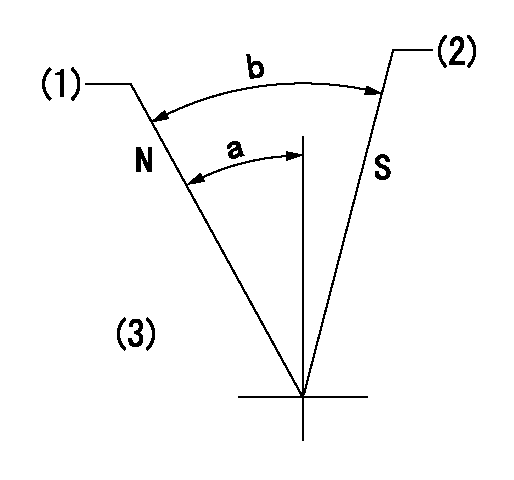
Speed control lever angle

N:Pump normal
S:Stop the pump.
(1)Rack position = aa
(2)Rack position bb
(3)1. After confirming that the rack is adjusted to cc, set the rack limit. 2. Set the rack limit so that R = dd.
----------
aa=16mm bb=1mm cc=16mm dd=14.5-0.2mm
----------
a=19deg+-5deg b=29deg+-5deg
----------
aa=16mm bb=1mm cc=16mm dd=14.5-0.2mm
----------
a=19deg+-5deg b=29deg+-5deg
0000000901

(1)Pump vertical direction
(2)Coupling's key groove position at No 1 cylinder's beginning of injection
(3)-
(4)-
----------
----------
a=(40deg)
----------
----------
a=(40deg)
Stop lever angle

(Rs) rack sensor specifications
(C/U) control unit part number
(V) Rack sensor output voltage
(R) Rack position (mm)
1. Confirming governor output characteristics (rack 15 mm, span 6 mm)
(1)When the output voltages of the rack sensor are V1 and V2, check that the rack positions R1 and R2 in the table above are satisfied.
----------
----------
----------
----------
Information:
2. Disconnect the fuel lines from fuel transfer pump (1).3. Remove two bolts (2) and fuel transfer pump (1). 4. Be sure O-ring seal (3) is in position on the fuel transfer pump and put clean oil on the O-ring seal.5. Put the fuel transfer pump in position on the fuel injection pump and install the two bolts that hold it in place.6. Connect the fuel lines to the fuel transfer pump.7. Open the fuel shutoff valve at the fuel tank.Disassemble Fuel Transfer Pump
start by:a) remove fuel transfer pump
Cover (2) is under spring tension.
1. Carefully remove bolts (1) and cover (2) from the fuel transfer pump. 2. Remove spring (3), valve (4) and O-ring seals (5) from the cover. 3. Remove springs (6) and (7) from the pump housing. 4. Remove sleeve (8) from the pump housing. 5. Remove sleeve (12), piston (16), O-ring seal (11) and piston (9) from sleeve (8). Remove plate (15), valve (10) and seal (14) from piston (9). Remove O-ring seal (13) from sleeve (8). 6. Remove O-ring seal (17) from the pump housing. 7. Push guide (18) through the pump housing and remove guides (23) and (18) together. Remove rod (20), guide (23), O-ring seal (19) and tappet (21) from guide (18). Remove ring (22) from tappet (21). 8. Remove connector (24), valve (26) and seal (25) from the pump housing. 9. Remove plug (30), spring (28), valve (29) and seal (27) from the pump housing.Assemble Fuel Transfer Pump
1. Clean all parts and be sure all passage are open. 2. Be sure the O-ring seal is in position on plug (4) and put 4L7464 Silicone Grease on the O-ring seal. Valves (2 and 6) must be installed as shown for the pump to work correctly.3. Install seal (1), valve (2), spring (3) and plug (4) in the pump housing as shown. Tighten plug (4) to a torque of 20 7 N m (15 5 lb.ft.). 4. Be sure the O-ring seal is in position on connector (7) and put 4L7464 Silicone Grease on the O-ring seal.5. Install seal (5), valve (6) and connector (7) in the pump housing as shown. Tighten connector (7) to a torque of 55 10 N m (40 7 lb.ft.). 6. Install the ring on tappet (8). Install tappet (8), O-ring seal (12), guide (9) and rod (10) in guide (11). Put 4L7464 Silicone Grease on O-ring seal (12). Install guides (11) and (9) as a unit in the pump housing as shown. 7. Install O-ring seal (13) in the pump housing and put 4L7464 Silicone Grease on the O-ring seal. 8. Install seal (15), valve (19) and plate (16) in piston (14) as shown. Install piston (14), O-ring seal (17), piston (20) and guide (21) in guide (18) as shown. Install the O-ring seal on guide (18) and put 4L7464 Silicone Grease on O-ring seal (17) and the O-ring seal on guide (18). 9. Install guide (18) in the pump housing as shown.
Have questions with 106861-2660?
Group cross 106861-2660 ZEXEL
Mitsubishi
Mitsubishi
Mitsubishi
Mitsubishi
106861-2660
F 019 Z10 232
ME442876
INJECTION-PUMP ASSEMBLY
8DC9TL
8DC9TL
