Information injection-pump assembly
BOSCH
F 01G 09U 09G
f01g09u09g
ZEXEL
106861-2601
1068612601
Rating:
Service parts 106861-2601 INJECTION-PUMP ASSEMBLY:
1.
_
7.
COUPLING PLATE
8.
_
9.
_
11.
Nozzle and Holder
ME066034
12.
Open Pre:MPa(Kqf/cm2)
21.6{220}
15.
NOZZLE SET
Include in #1:
106861-2601
as INJECTION-PUMP ASSEMBLY
Cross reference number
BOSCH
F 01G 09U 09G
f01g09u09g
ZEXEL
106861-2601
1068612601
Zexel num
Bosch num
Firm num
Name
Calibration Data:
Adjustment conditions
Test oil
1404 Test oil ISO4113 or {SAEJ967d}
1404 Test oil ISO4113 or {SAEJ967d}
Test oil temperature
degC
40
40
45
Nozzle and nozzle holder
105780-8140
Bosch type code
EF8511/9A
Nozzle
105780-0000
Bosch type code
DN12SD12T
Nozzle holder
105780-2080
Bosch type code
EF8511/9
Opening pressure
MPa
17.2
Opening pressure
kgf/cm2
175
Injection pipe
Outer diameter - inner diameter - length (mm) mm 8-3-600
Outer diameter - inner diameter - length (mm) mm 8-3-600
Overflow valve
131424-4620
Overflow valve opening pressure
kPa
255
221
289
Overflow valve opening pressure
kgf/cm2
2.6
2.25
2.95
Tester oil delivery pressure
kPa
157
157
157
Tester oil delivery pressure
kgf/cm2
1.6
1.6
1.6
Direction of rotation (viewed from drive side)
Right R
Right R
Injection timing adjustment
Direction of rotation (viewed from drive side)
Right R
Right R
Injection order
1-2-7-3-
4-5-6-8
Pre-stroke
mm
4.8
4.75
4.85
Beginning of injection position
Governor side NO.1
Governor side NO.1
Difference between angles 1
Cyl.1-2 deg. 45 44.5 45.5
Cyl.1-2 deg. 45 44.5 45.5
Difference between angles 2
Cal 1-7 deg. 90 89.5 90.5
Cal 1-7 deg. 90 89.5 90.5
Difference between angles 3
Cal 1-3 deg. 135 134.5 135.5
Cal 1-3 deg. 135 134.5 135.5
Difference between angles 4
Cal 1-4 deg. 180 179.5 180.5
Cal 1-4 deg. 180 179.5 180.5
Difference between angles 5
Cal 1-5 deg. 225 224.5 225.5
Cal 1-5 deg. 225 224.5 225.5
Difference between angles 6
Cal 1-6 deg. 270 269.5 270.5
Cal 1-6 deg. 270 269.5 270.5
Difference between angles 7
Cal 1-8 deg. 315 314.5 315.5
Cal 1-8 deg. 315 314.5 315.5
Injection quantity adjustment
Adjusting point
A
Rack position
10.7
Pump speed
r/min
850
850
850
Average injection quantity
mm3/st.
133.5
130.5
136.5
Max. variation between cylinders
%
0
-3
3
Basic
*
Fixing the lever
*
Injection quantity adjustment_02
Adjusting point
B
Rack position
4.9+-0.5
Pump speed
r/min
275
275
275
Average injection quantity
mm3/st.
15.5
12.9
18.1
Max. variation between cylinders
%
0
-15
15
Fixing the rack
*
Injection quantity adjustment_03
Adjusting point
D
Rack position
-
Pump speed
r/min
100
100
100
Average injection quantity
mm3/st.
135
135
145
Fixing the lever
*
Rack limit
*
Timer adjustment
Pump speed
r/min
(N1+50)-
-
Advance angle
deg.
0
0
0
Remarks
Start
Start
Timer adjustment_02
Pump speed
r/min
N1
Advance angle
deg.
0.5
Remarks
Measure the actual speed.
Measure the actual speed.
Timer adjustment_03
Pump speed
r/min
900
Remarks
Measure the actual advance angle.
Measure the actual advance angle.
Timer adjustment_04
Pump speed
r/min
-
Advance angle
deg.
3
3
3
Remarks
Measure the actual speed, stop
Measure the actual speed, stop
Test data Ex:
Governor adjustment
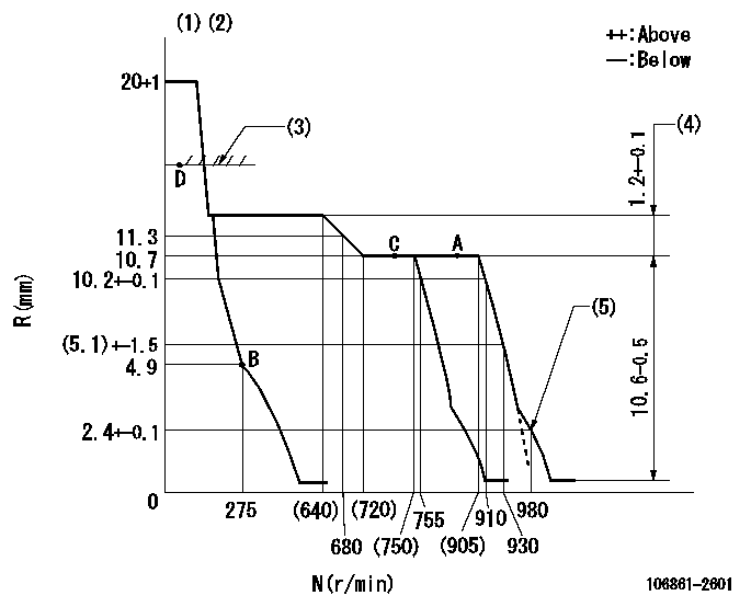
N:Pump speed
R:Rack position (mm)
(1)Notch fixed: K
(2)Tolerance for racks not indicated: +-0.05mm.
(3)RACK LIMIT
(4)Rack difference between N = N1 and N = N2
(5)Set idle sub-spring
----------
K=11 N1=850r/min N2=500r/min
----------
----------
K=11 N1=850r/min N2=500r/min
----------
Speed control lever angle
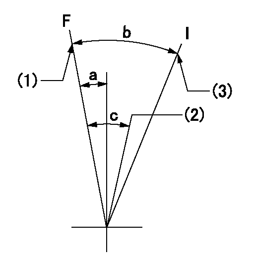
F:Full speed
I:Idle
(1)Set the pump speed at aa
(2)Set the pump speed at bb.
(3)Stopper bolt setting
----------
aa=910r/min bb=755r/min
----------
a=(1deg)+-5deg b=(30deg)+-5deg c=(7deg)+-5deg
----------
aa=910r/min bb=755r/min
----------
a=(1deg)+-5deg b=(30deg)+-5deg c=(7deg)+-5deg
Stop lever angle
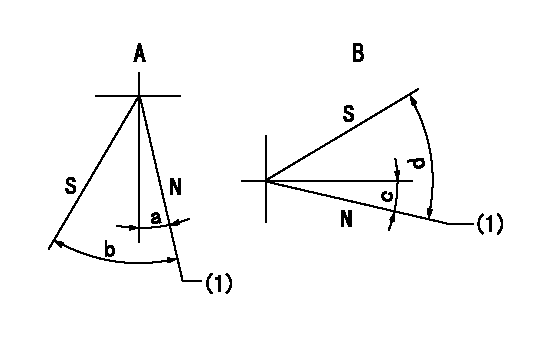
N:Pump normal
S:Stop the pump.
A:Right front
B:Right rear
(1)Normal
----------
----------
a=19deg+-5deg b=46deg+-5deg c=28deg+-5deg d=53deg+-5deg
----------
----------
a=19deg+-5deg b=46deg+-5deg c=28deg+-5deg d=53deg+-5deg
Timing setting

(1)Pump vertical direction
(2)Coupling's key groove position at No 1 cylinder's beginning of injection
(3)-
(4)-
----------
----------
a=(40deg)
----------
----------
a=(40deg)
Information:
You must read and understand the warnings and instructions contained in the Safety section of this manual before performing any operation or maintenance procedures.Before proceeding with this maintenance, perform all previous maintenance interval requirements.Cooling System (Extended Life Coolant Only)
Do not perform this maintenance until you read and understand the material in the Safety and Cooling System Specifications sections of this publication.
Drain/Flush/Replace Coolant
Caterpillar Extended Life Coolant should be replaced every 6,000 Service Hours or 4 Years, whichever comes first. Only clean water is needed to clean and flush the cooling system when ELC is drained and replaced.Drain
1. Stop the engine and allow the engine to cool. Loosen the coolant filler cap slowly to relieve any pressure, and remove the cap.2. Remove the cooling system drain plug(s) or open the drain valve. Remove the drain plug from the bottom of the water pump housing (if equipped) and/or radiator. Allow the coolant to drain.
Dispose of used engine coolant properly or recycle. Various methods have been proposed to reclaim used coolant for reuse in engine cooling systems. The full distillation procedure is the only method acceptable by Caterpillar to reclaim the used coolant. Contact your Caterpillar dealer for information regarding disposal and recycling of used coolant.
Contact Caterpillar Service Technology Group:Outside Illinois: 1-800-542-TOOLInside Illinois: 1-800-541-TOOLCanada: 1-800-523-TOOLFlush
4. Flush the cooling system with clean water to remove any debris.5. Clean and install all drain plugs and/or close the drain valve(s).6. Fill the cooling system with clean water. Install the filler cap. Operate the engine until warm 49 to 66°C (150 to 120°F).7. Stop the engine and allow the engine to cool. Loosen the coolant filler cap slowly to relieve any pressure, and remove the cap. Remove the cooling system drain plug(s) or open the drain valve. Allow the water to drain. Flush the cooling system with clean water.8. Repeat steps 6 and 7.Fill
9. Fill the cooling system with ELC. Refer to the refill capacities chart in this manual for the amount of ELC needed to refill your system.10. Start and run the engine with the filler cap removed. Allow the ELC to warm, the thermostat to open, and the coolant level to stabilize. Add ELC if necessary to bring the coolant to the proper level.11. Check the condition of the filler cap gasket. If the gasket is damaged, discard the old filler cap and install a new filler cap. If the gasket is not damaged, use a 9S8140 Service Tool (available from your Caterpillar dealer) to pressure test the filler cap. The correct filler cap pressure is stamped on the face of the filler cap. If the filler cap does not hold the correct pressure, install a new filler cap.12. Start the engine and inspect for coolant leaks and proper operating temperature. Stop the engine.
