Information injection-pump assembly
BOSCH
9 400 611 010
9400611010
ZEXEL
106861-2560
1068612560
MITSUBISHI
ME098730
me098730
Rating:
Service parts 106861-2560 INJECTION-PUMP ASSEMBLY:
1.
_
7.
COUPLING PLATE
8.
_
9.
_
11.
Nozzle and Holder
ME066034
12.
Open Pre:MPa(Kqf/cm2)
21.6{220}

15.
NOZZLE SET
Include in #1:
106861-2560
as INJECTION-PUMP ASSEMBLY
Cross reference number
BOSCH
9 400 611 010
9400611010
ZEXEL
106861-2560
1068612560
MITSUBISHI
ME098730
me098730
Zexel num
Bosch num
Firm num
Name
106861-2560
9 400 611 010
ME098730 MITSUBISHI
INJECTION-PUMP ASSEMBLY
8DC90PT * K
8DC90PT * K
Calibration Data:
Adjustment conditions
Test oil
1404 Test oil ISO4113 or {SAEJ967d}
1404 Test oil ISO4113 or {SAEJ967d}
Test oil temperature
degC
40
40
45
Nozzle and nozzle holder
105780-8140
Bosch type code
EF8511/9A
Nozzle
105780-0000
Bosch type code
DN12SD12T
Nozzle holder
105780-2080
Bosch type code
EF8511/9
Opening pressure
MPa
17.2
Opening pressure
kgf/cm2
175
Injection pipe
Outer diameter - inner diameter - length (mm) mm 8-3-600
Outer diameter - inner diameter - length (mm) mm 8-3-600
Overflow valve
131424-4620
Overflow valve opening pressure
kPa
255
221
289
Overflow valve opening pressure
kgf/cm2
2.6
2.25
2.95
Tester oil delivery pressure
kPa
157
157
157
Tester oil delivery pressure
kgf/cm2
1.6
1.6
1.6
Direction of rotation (viewed from drive side)
Right R
Right R
Injection timing adjustment
Direction of rotation (viewed from drive side)
Right R
Right R
Injection order
1-2-7-3-
4-5-6-8
Pre-stroke
mm
4.8
4.75
4.85
Beginning of injection position
Governor side NO.1
Governor side NO.1
Difference between angles 1
Cyl.1-2 deg. 45 44.5 45.5
Cyl.1-2 deg. 45 44.5 45.5
Difference between angles 2
Cal 1-7 deg. 90 89.5 90.5
Cal 1-7 deg. 90 89.5 90.5
Difference between angles 3
Cal 1-3 deg. 135 134.5 135.5
Cal 1-3 deg. 135 134.5 135.5
Difference between angles 4
Cal 1-4 deg. 180 179.5 180.5
Cal 1-4 deg. 180 179.5 180.5
Difference between angles 5
Cal 1-5 deg. 225 224.5 225.5
Cal 1-5 deg. 225 224.5 225.5
Difference between angles 6
Cal 1-6 deg. 270 269.5 270.5
Cal 1-6 deg. 270 269.5 270.5
Difference between angles 7
Cal 1-8 deg. 315 314.5 315.5
Cal 1-8 deg. 315 314.5 315.5
Injection quantity adjustment
Adjusting point
A
Rack position
11
Pump speed
r/min
850
850
850
Average injection quantity
mm3/st.
136.3
133.3
139.3
Max. variation between cylinders
%
0
-3
3
Basic
*
Fixing the lever
*
Injection quantity adjustment_02
Adjusting point
B
Rack position
10.4
Pump speed
r/min
900
900
900
Average injection quantity
mm3/st.
124
120
128
Max. variation between cylinders
%
0
-4
4
Fixing the lever
*
Injection quantity adjustment_03
Adjusting point
C
Rack position
5.3+-0.5
Pump speed
r/min
250
250
250
Average injection quantity
mm3/st.
18.5
15.9
21.1
Max. variation between cylinders
%
0
-15
15
Fixing the rack
*
Timer adjustment
Pump speed
r/min
900--
Advance angle
deg.
0
0
0
Remarks
Start
Start
Timer adjustment_02
Pump speed
r/min
850
Advance angle
deg.
0.5
Timer adjustment_03
Pump speed
r/min
900
Advance angle
deg.
0.8
Timer adjustment_04
Pump speed
r/min
-
Advance angle
deg.
3
2.5
3.5
Remarks
Measure the actual speed, stop
Measure the actual speed, stop
Test data Ex:
Governor adjustment
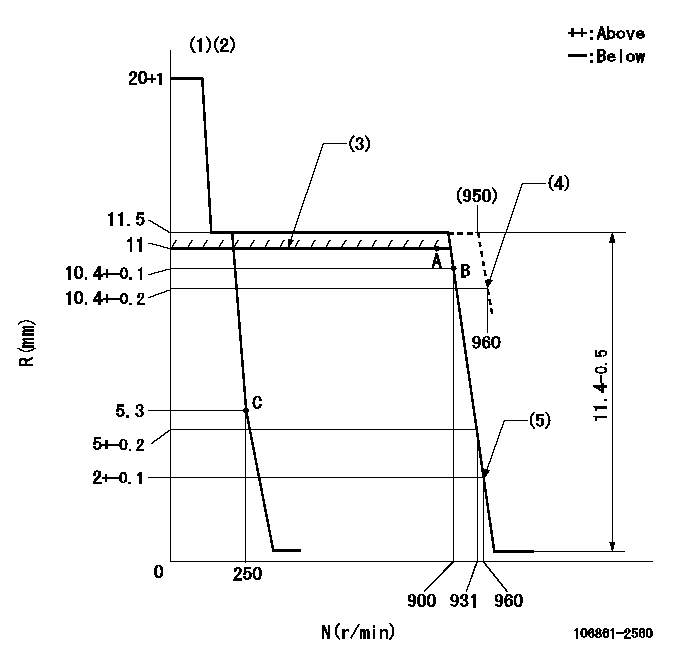
N:Pump speed
R:Rack position (mm)
(1)Target notch: K
(2)Tolerance for racks not indicated: +-0.05mm.
(3)RACK LIMIT
(4)Set at delivery
(5)Set idle sub-spring
----------
K=12
----------
----------
K=12
----------
Speed control lever angle

F:Full speed
I:Idle
(1)Stopper bolt setting
(2)At delivery
----------
----------
a=3deg+-5deg b=27deg+-5deg c=(2deg)
----------
----------
a=3deg+-5deg b=27deg+-5deg c=(2deg)
Stop lever angle

N:Pump normal
S:Stop the pump.
----------
----------
a=19deg+-5deg b=46deg+-5deg
----------
----------
a=19deg+-5deg b=46deg+-5deg
Timing setting

(1)Pump vertical direction
(2)Coupling's key groove position at No 1 cylinder's beginning of injection
(3)-
(4)-
----------
----------
a=(40deg)
----------
----------
a=(40deg)
Information:
You must read and understand the warnings and instructions contained in the Safety section of this manual before performing any operation or maintenance procedures.Before proceeding with Every 50 Hour maintenance, perform all Daily maintenance requirements.Dust Collector
Never run the engine without an air cleaner installed. Never run the engine with a damaged air cleaner. Do not use filter elements with damaged pleats, gaskets or seals. Dirt entering the engine causes premature wear and damage to engine components. Air cleaners prevent airborne debris from entering the engine through the air inlet.
Clean
Typical two stage air cleaner. Individual applications may be different.1. Remove the air cleaner cap (1). Remove the dust collector cup (2).2. Wipe dust collector cup with a clean, dry cloth.3. Install the cup. Install and secure the cap. If equipped with a heavy duty air cleaner: refer to the Heavy Duty Air Cleaner topic in the Daily section of this manual for information about cleaning the dust collector cup.Light Duty Air Cleaner (If Equipped)
Light duty air cleaners are not serviceable (washable). Light duty air cleaners are intended for a 50 service hours of maximum use, or one year, whichever occurs first. However, engines operating in a severe environment may require more frequent air cleaner replacement.Dust conditions vary for different operating environments. Service the air cleaner at regular intervals as determined by the operating environment. Check the air cleaner service indicator (if equipped) daily.Check the air cleaner for cleanliness and damage such as rips and tears. Replace the air cleaner element at the required service interval, or more often as determined by the operating environmental dust conditions. To Replace the Light Duty Air Cleaner Element: 1. Loosen the clamp (2) fastening the air cleaner element (1) to the air inlet, and remove the dirty element and clamp.2. Install the clamp on a new element.3. Install the new element to the air inlet and tighten the clamp.
Have questions with 106861-2560?
Group cross 106861-2560 ZEXEL
Mitsubishi
Mitsubishi
Mitsubishi
106861-2560
9 400 611 010
ME098730
INJECTION-PUMP ASSEMBLY
8DC90PT
8DC90PT