Information injection-pump assembly
BOSCH
9 400 617 996
9400617996
ZEXEL
106861-2540
1068612540
MITSUBISHI
ME098650
me098650
Rating:
Service parts 106861-2540 INJECTION-PUMP ASSEMBLY:
1.
_
7.
COUPLING PLATE
8.
_
9.
_
11.
Nozzle and Holder
12.
Open Pre:MPa(Kqf/cm2)
21.6{220}

15.
NOZZLE SET
Include in #1:
106861-2540
as INJECTION-PUMP ASSEMBLY
Cross reference number
BOSCH
9 400 617 996
9400617996
ZEXEL
106861-2540
1068612540
MITSUBISHI
ME098650
me098650
Zexel num
Bosch num
Firm num
Name
106861-2540
9 400 617 996
ME098650 MITSUBISHI
INJECTION-PUMP ASSEMBLY
8DC9T * K 14CD INJECTION PUMP ASSY PE8P PE
8DC9T * K 14CD INJECTION PUMP ASSY PE8P PE
Calibration Data:
Adjustment conditions
Test oil
1404 Test oil ISO4113 or {SAEJ967d}
1404 Test oil ISO4113 or {SAEJ967d}
Test oil temperature
degC
40
40
45
Nozzle and nozzle holder
105780-8140
Bosch type code
EF8511/9A
Nozzle
105780-0000
Bosch type code
DN12SD12T
Nozzle holder
105780-2080
Bosch type code
EF8511/9
Opening pressure
MPa
17.2
Opening pressure
kgf/cm2
175
Injection pipe
Outer diameter - inner diameter - length (mm) mm 8-3-600
Outer diameter - inner diameter - length (mm) mm 8-3-600
Overflow valve
131424-4620
Overflow valve opening pressure
kPa
255
221
289
Overflow valve opening pressure
kgf/cm2
2.6
2.25
2.95
Tester oil delivery pressure
kPa
157
157
157
Tester oil delivery pressure
kgf/cm2
1.6
1.6
1.6
Direction of rotation (viewed from drive side)
Right R
Right R
Injection timing adjustment
Direction of rotation (viewed from drive side)
Right R
Right R
Injection order
1-2-7-3-
4-5-6-8
Pre-stroke
mm
4.8
4.75
4.85
Beginning of injection position
Governor side NO.1
Governor side NO.1
Difference between angles 1
Cyl.1-2 deg. 45 44.5 45.5
Cyl.1-2 deg. 45 44.5 45.5
Difference between angles 2
Cal 1-7 deg. 90 89.5 90.5
Cal 1-7 deg. 90 89.5 90.5
Difference between angles 3
Cal 1-3 deg. 135 134.5 135.5
Cal 1-3 deg. 135 134.5 135.5
Difference between angles 4
Cal 1-4 deg. 180 179.5 180.5
Cal 1-4 deg. 180 179.5 180.5
Difference between angles 5
Cal 1-5 deg. 225 224.5 225.5
Cal 1-5 deg. 225 224.5 225.5
Difference between angles 6
Cal 1-6 deg. 270 269.5 270.5
Cal 1-6 deg. 270 269.5 270.5
Difference between angles 7
Cal 1-8 deg. 315 314.5 315.5
Cal 1-8 deg. 315 314.5 315.5
Injection quantity adjustment
Adjusting point
A
Rack position
9.3
Pump speed
r/min
900
900
900
Average injection quantity
mm3/st.
131
128
134
Max. variation between cylinders
%
0
-3
3
Basic
*
Fixing the lever
*
Injection quantity adjustment_02
Adjusting point
B
Rack position
6.1+-0.5
Pump speed
r/min
275
275
275
Average injection quantity
mm3/st.
11.4
8.8
14
Max. variation between cylinders
%
0
-15
15
Fixing the rack
*
Timer adjustment
Pump speed
r/min
1100++
Advance angle
deg.
0
0
0
Remarks
Do not advance until starting N = 1100.
Do not advance until starting N = 1100.
Timer adjustment_02
Pump speed
r/min
-
Advance angle
deg.
3.5
3.5
3.5
Remarks
Measure the actual speed, stop
Measure the actual speed, stop
Test data Ex:
Governor adjustment
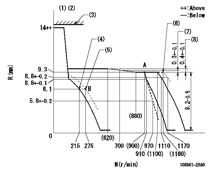
N:Pump speed
R:Rack position (mm)
(1)Target notch: K
(2)Tolerance for racks not indicated: +-0.05mm.
(3)Rack limit (operating at delivery)
(4)Main spring setting
(5)Set idle sub-spring
(6)At shipping
(7)Rack difference between N = N1 and N = N2
(8)Rack difference between N = N3 and N = N4
----------
K=16 N1=900r/min N2=700r/min N3=900r/min N4=500r/min
----------
----------
K=16 N1=900r/min N2=700r/min N3=900r/min N4=500r/min
----------
Speed control lever angle
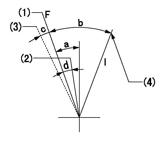
F:Full speed
I:Idle
(1)Pump speed = aa
(2)Set the pump speed at bb.
(3)At shipping
(4)Stopper bolt setting
----------
aa=1100r/min bb=910r/min
----------
a=10deg+-5deg b=25deg+-5deg c=(2deg) d=6deg+-5deg
----------
aa=1100r/min bb=910r/min
----------
a=10deg+-5deg b=25deg+-5deg c=(2deg) d=6deg+-5deg
Stop lever angle
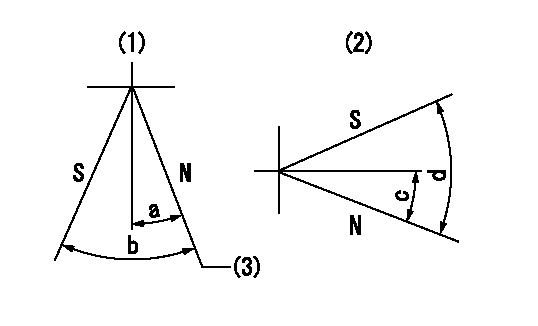
N:Pump normal
S:Stop the pump.
(1)Right front
(2)Right rear
(3)Normal
----------
----------
a=19deg+-5deg b=46deg+-5deg c=28deg+-5deg d=53deg+-5deg
----------
----------
a=19deg+-5deg b=46deg+-5deg c=28deg+-5deg d=53deg+-5deg
Timing setting

(1)Pump vertical direction
(2)Coupling's key groove position at No 1 cylinder's beginning of injection
(3)-
(4)-
----------
----------
a=(40deg)
----------
----------
a=(40deg)
Information:
Use fuel consumption or service hours, whichever occurs first, to determine maintenance intervals. Experience has shown that maintenance intervals are most accurately scheduled on the basis of fuel consumed rather than service hours.Daily
Walk-Around Inspection - Inspect engine for leaks and loose connections Engine Crankcase - Check oil level Cooling System - Check coolant level Clutch - Check/Adjust/Lubricate Air Starter & Air Tank (if equipped) - Check Engine Air Cleaner - Check service indicator SR4 Generator - Inspect/CheckEvery 1,900 L (500 gal) of Fuel or 50 Service Hours*
Dust Collector - Clean Light Duty Air Cleaner (If Equipped) - ReplaceEvery 4,250 L (1,100 gal) of Fuel or 125 Service Hours*
Clutch - Check/Adjust/Lubricate Generator Space Heaters - CheckEvery 8,500 L (2,200 gal) of Fuel or 250 Service Hours*
Scheduled Oil Sampling (S O S)1 - Obtain Sample Engine Oil and Filter(s)1 - Change Crankcase Breather1 - Clean Engine Valve Lash (Between First 250 and 1000 Service Hours Only)1 - Check/Adjust Cooling System - Test for supplemental coolant additive concentration Fuel System - Clean/Replace filters, Drain water from fuel tank Radiator Fins, Aftercooler, Belts, and Hoses - Inspect/Check Fan Drive Bearing - Lubricate Batteries - Clean/Check Magnetic Pickup (At First Oil Change Only - Inspect/Clean1These maintenance requirements are to be performed between the 250 and the 1000 Service Hour interval for engines equipped with turbochargers (T, TA & ATAAC) ONLY. Refer to 500 Hour interval for Naturally Aspirated (NA) Engines.Every 17,000 L (4,500 gal) of Fuel or 500 Service Hours (NA Only)*
Scheduled Oil Sampling (S O S) - Obtain Sample Engine Oil and Filter(s) - Change Crankcase Breather - Clean Engine Valve Lash (Between First 500 and 1000 Service Hours Only) - Check/AdjustEvery 34,000 L (9,000 gal) of Fuel or 1000 Service Hours*
Engine Protection Devices - Inspect SR4 Generator and Control Panel - Inspect Fuel Control Linkage - LubricateEvery 67,000 L (18,000 gal) of Fuel or 2000 Service Hours*
Engine Valve Lash, Valve Rotators, Fuel Ratio Control, Set Point, and Low Idle - Check/Adjust Fuel Injection Nozzles - Test/Clean/Replace Turbocharger - Inspect Engine Mounts - Inspect Crankshaft Vibration Damper - Inspect SR4 Generator - Check/Inspect Clean/LubricateEvery 91,000 L (24,000 gal) of Fuel or 3000 Service Hours or Two Years*
Cooling System - Add Extender (Extended Life Coolant Only) - Cooling System - Drain/Clean/Replace Coolant - Conventional Coolant/Antifreeze Only Water Pump Seal - Inspect/Replace Hoses - Replace Thermostat - ReplaceEvery 136,000 L (36,000 gal) of Fuel or 4000 Service Hours*
Magnetic Pickup - Inspect/Clean SR4 Generator - Check/Inspect/Clean/LubricateEvery 204,000 L (54,000 gal) of Fuel or 6,000 Service Hours or Four Years
Cooling System - Drain/Flush/Replace Coolant (Extended Life Coolant Only)*Perform previous maintenance interval items first.
Have questions with 106861-2540?
Group cross 106861-2540 ZEXEL
Mitsubishi
Mitsubishi
Mitsubishi
106861-2540
9 400 617 996
ME098650
INJECTION-PUMP ASSEMBLY
8DC9T
8DC9T