Information injection-pump assembly
BOSCH
F 019 Z20 225
f019z20225
ZEXEL
106861-2492
1068612492
MITSUBISHI
ME442585
me442585
Rating:
Service parts 106861-2492 INJECTION-PUMP ASSEMBLY:
1.
_
7.
COUPLING PLATE
8.
_
9.
_
11.
Nozzle and Holder
12.
Open Pre:MPa(Kqf/cm2)
21.6(220)

15.
NOZZLE SET
Include in #1:
106861-2492
as INJECTION-PUMP ASSEMBLY
Cross reference number
BOSCH
F 019 Z20 225
f019z20225
ZEXEL
106861-2492
1068612492
MITSUBISHI
ME442585
me442585
Zexel num
Bosch num
Firm num
Name
106861-2492
F 019 Z20 225
ME442585 MITSUBISHI
INJECTION-PUMP ASSEMBLY
8DC9T K 14CD INJECTION PUMP ASSY PE8P PE
8DC9T K 14CD INJECTION PUMP ASSY PE8P PE
Calibration Data:
Adjustment conditions
Test oil
1404 Test oil ISO4113 or {SAEJ967d}
1404 Test oil ISO4113 or {SAEJ967d}
Test oil temperature
degC
40
40
45
Nozzle and nozzle holder
105780-8140
Bosch type code
EF8511/9A
Nozzle
105780-0000
Bosch type code
DN12SD12T
Nozzle holder
105780-2080
Bosch type code
EF8511/9
Opening pressure
MPa
17.2
Opening pressure
kgf/cm2
175
Injection pipe
Outer diameter - inner diameter - length (mm) mm 8-3-600
Outer diameter - inner diameter - length (mm) mm 8-3-600
Overflow valve
131424-4620
Overflow valve opening pressure
kPa
255
221
289
Overflow valve opening pressure
kgf/cm2
2.6
2.25
2.95
Tester oil delivery pressure
kPa
157
157
157
Tester oil delivery pressure
kgf/cm2
1.6
1.6
1.6
Direction of rotation (viewed from drive side)
Right R
Right R
Injection timing adjustment
Direction of rotation (viewed from drive side)
Right R
Right R
Injection order
1-2-7-3-
4-5-6-8
Pre-stroke
mm
4.8
4.75
4.85
Beginning of injection position
Governor side NO.1
Governor side NO.1
Difference between angles 1
Cyl.1-2 deg. 45 44.75 45.25
Cyl.1-2 deg. 45 44.75 45.25
Difference between angles 2
Cal 1-7 deg. 90 89.75 90.25
Cal 1-7 deg. 90 89.75 90.25
Difference between angles 3
Cal 1-3 deg. 135 134.75 135.25
Cal 1-3 deg. 135 134.75 135.25
Difference between angles 4
Cal 1-4 deg. 180 179.75 180.25
Cal 1-4 deg. 180 179.75 180.25
Difference between angles 5
Cal 1-5 deg. 225 224.75 225.25
Cal 1-5 deg. 225 224.75 225.25
Difference between angles 6
Cal 1-6 deg. 270 269.75 270.25
Cal 1-6 deg. 270 269.75 270.25
Difference between angles 7
Cal 1-8 deg. 315 314.75 315.25
Cal 1-8 deg. 315 314.75 315.25
Injection quantity adjustment
Adjusting point
A
Rack position
13.2
Pump speed
r/min
850
850
850
Average injection quantity
mm3/st.
181
178
184
Max. variation between cylinders
%
0
-3
3
Basic
*
Fixing the lever
*
Injection quantity adjustment_02
Adjusting point
B
Rack position
5.3+-0.5
Pump speed
r/min
250
250
250
Average injection quantity
mm3/st.
18.5
15.9
21.1
Max. variation between cylinders
%
0
-15
15
Fixing the rack
*
Injection quantity adjustment_03
Adjusting point
C
Rack position
12.7
Pump speed
r/min
900
900
900
Average injection quantity
mm3/st.
174
170
178
Max. variation between cylinders
%
0
-4
4
Fixing the lever
*
Timer adjustment
Pump speed
r/min
850++
Advance angle
deg.
0
0
0
Remarks
Do not advance until starting N = 850.
Do not advance until starting N = 850.
Timer adjustment_02
Pump speed
r/min
-
Advance angle
deg.
3
3
3
Remarks
Measure the actual speed, stop
Measure the actual speed, stop
Test data Ex:
Governor adjustment
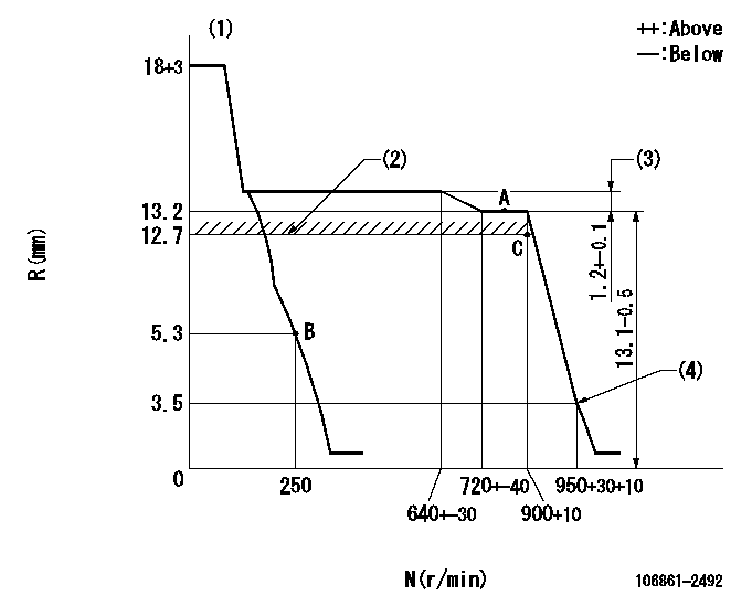
N:Pump speed
R:Rack position (mm)
(1)Target notch: K
(2)RACK LIMIT
(3)Rack difference between N = N1 and N = N2
(4)Idle sub spring setting: L1.
----------
K=11 N1=850r/min N2=500r/min L1=3.5+0.2-0.3mm
----------
----------
K=11 N1=850r/min N2=500r/min L1=3.5+0.2-0.3mm
----------
Speed control lever angle

F:Full speed
I:Idle
(1)Stopper bolt setting
----------
----------
a=5deg+-5deg b=28deg+-5deg
----------
----------
a=5deg+-5deg b=28deg+-5deg
Stop lever angle
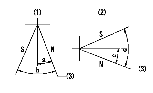
N:Pump normal
S:Stop the pump.
(1)Right front
(2)Right rear
(3)Normal
----------
----------
a=19deg+-5deg b=46deg+-5deg c=28deg+-5deg d=53deg+-5deg
----------
----------
a=19deg+-5deg b=46deg+-5deg c=28deg+-5deg d=53deg+-5deg
Timing setting

(1)Pump vertical direction
(2)Coupling's key groove position at No 1 cylinder's beginning of injection
(3)-
(4)-
----------
----------
a=(40deg)
----------
----------
a=(40deg)
Information:
Stopping the engine immediately after it has been working under load can result in overheating and accelerated wear of the engine components. Allow the engine to engine cool down before stopping. Avoiding hot engine shutdowns will maximize turbocharger shaft and bearing life.
If the engine has been operating at high load, run at low idle for at least three minutes before stopping. This cool down will reduce and stabilize internal engine coolant and oil temperatures before stopping the engine.If the engine has been operating at low loads, run the engine at low idle for 30 seconds before stopping.Make sure the shutoff procedure is understood. Refer to the Stopping the Engine instructions in the Generator Set Control Panel topic in this publication. Use the following general guidelines for stopping the engine.1. Open the Main electrical circuit breaker/Remove load from engine.2. Move the governor control to no more than half engine speed. Run the engine for three to five minutes.3. Reduce the engine speed to low idle.4. The engine may be stopped by using the Woodward Governor (if equipped), the Mechanical Governor (if equipped), or the solenoid shutoff switch.Woodward Actuator (If Equipped)
If equipped with a Woodward Actuator, move the control lever upward or forward, depending on the installation. Hold the lever to the OFF or STOP position until the engine stops.Mechanical Governor Control
A manual shutoff lever is provided to shut off the fuel from the fuel injection pump and override the governor control. The manual shutoff lever is located on the side of the pump.The engine can be shut OFF by rotating and holding the manual shutoff lever in the clockwise (CW) direction. If equipped with a Mechanical Governor Control, to move control to the SHUT OFF position: pull upward on the vernier hand grip while pushing down on thumb button. This shutdown will only move the fuel control linkage (rack) to the FUEL-OFF position. This does not shut off the air inlet.Solenoid Shutoff
Move the Control Panel Engine Control Switch (ECS, if equipped) to the STOP position.After Stopping the Engine
1. Fill the fuel tank to prevent accumulation of moisture in the fuel.2. Check the coolant level. Maintain the cooling system to 13 mm (1/2 inch) from bottom of the fill pipe. If freezing temperatures are expected, allow the radiator and engine jacket water system to cool, then check the coolant for proper antifreeze protection. The cooling system must be protected against freezing to the lowest expected ambient (outside) temperature. Add the proper coolant and water mixture if necessary.3. Check the crankcase oil level. Maintain the oil level between the ADD and FULL marks in the FULL RANGE zone on the dipstick.4. Repair any leaks, perform minor adjustments, tighten loose bolts, etc. 5. Note the service hour meter reading. Perform periodic maintenance as instructed in the Maintenance Schedule.
Have questions with 106861-2492?
Group cross 106861-2492 ZEXEL
Mitsubishi
Mitsubishi
Mitsubishi
106861-2492
F 019 Z20 225
ME442585
INJECTION-PUMP ASSEMBLY
8DC9T
8DC9T