Information injection-pump assembly
BOSCH
9 400 617 991
9400617991
ZEXEL
106861-2480
1068612480
MITSUBISHI
ME098599
me098599

Rating:
Service parts 106861-2480 INJECTION-PUMP ASSEMBLY:
1.
_
7.
COUPLING PLATE
8.
_
9.
_
11.
Nozzle and Holder
ME066034
12.
Open Pre:MPa(Kqf/cm2)
21.6{220}

15.
NOZZLE SET
Include in #1:
106861-2480
as INJECTION-PUMP ASSEMBLY
Cross reference number
BOSCH
9 400 617 991
9400617991
ZEXEL
106861-2480
1068612480
MITSUBISHI
ME098599
me098599
Zexel num
Bosch num
Firm num
Name
106861-2480
9 400 617 991
ME098599 MITSUBISHI
INJECTION-PUMP ASSEMBLY
8DC9T K 14CD INJECTION PUMP ASSY PE8P PE
8DC9T K 14CD INJECTION PUMP ASSY PE8P PE
Calibration Data:
Adjustment conditions
Test oil
1404 Test oil ISO4113 or {SAEJ967d}
1404 Test oil ISO4113 or {SAEJ967d}
Test oil temperature
degC
40
40
45
Nozzle and nozzle holder
105780-8140
Bosch type code
EF8511/9A
Nozzle
105780-0000
Bosch type code
DN12SD12T
Nozzle holder
105780-2080
Bosch type code
EF8511/9
Opening pressure
MPa
17.2
Opening pressure
kgf/cm2
175
Injection pipe
Outer diameter - inner diameter - length (mm) mm 8-3-600
Outer diameter - inner diameter - length (mm) mm 8-3-600
Overflow valve
131424-4620
Overflow valve opening pressure
kPa
255
221
289
Overflow valve opening pressure
kgf/cm2
2.6
2.25
2.95
Tester oil delivery pressure
kPa
157
157
157
Tester oil delivery pressure
kgf/cm2
1.6
1.6
1.6
Direction of rotation (viewed from drive side)
Right R
Right R
Injection timing adjustment
Direction of rotation (viewed from drive side)
Right R
Right R
Injection order
1-2-7-3-
4-5-6-8
Pre-stroke
mm
4.8
4.75
4.85
Beginning of injection position
Governor side NO.1
Governor side NO.1
Difference between angles 1
Cyl.1-2 deg. 45 44.5 45.5
Cyl.1-2 deg. 45 44.5 45.5
Difference between angles 2
Cal 1-7 deg. 90 89.5 90.5
Cal 1-7 deg. 90 89.5 90.5
Difference between angles 3
Cal 1-3 deg. 135 134.5 135.5
Cal 1-3 deg. 135 134.5 135.5
Difference between angles 4
Cal 1-4 deg. 180 179.5 180.5
Cal 1-4 deg. 180 179.5 180.5
Difference between angles 5
Cal 1-5 deg. 225 224.5 225.5
Cal 1-5 deg. 225 224.5 225.5
Difference between angles 6
Cal 1-6 deg. 270 269.5 270.5
Cal 1-6 deg. 270 269.5 270.5
Difference between angles 7
Cal 1-8 deg. 315 314.5 315.5
Cal 1-8 deg. 315 314.5 315.5
Injection quantity adjustment
Adjusting point
A
Rack position
9.6
Pump speed
r/min
700
700
700
Average injection quantity
mm3/st.
137.5
134.5
140.5
Max. variation between cylinders
%
0
-3
3
Basic
*
Fixing the lever
*
Injection quantity adjustment_02
Adjusting point
C
Rack position
6.3+-0.5
Pump speed
r/min
225
225
225
Average injection quantity
mm3/st.
12
9.4
14.6
Max. variation between cylinders
%
0
-15
15
Fixing the rack
*
Injection quantity adjustment_03
Adjusting point
D
Rack position
-
Pump speed
r/min
200
200
200
Average injection quantity
mm3/st.
205
185
225
Fixing the lever
*
Remarks
After startup boost setting
After startup boost setting
Timer adjustment
Pump speed
r/min
1100++
Advance angle
deg.
0
0
0
Remarks
Do not advance until starting N = 1100.
Do not advance until starting N = 1100.
Timer adjustment_02
Pump speed
r/min
-
Advance angle
deg.
3.5
3.5
3.5
Remarks
Measure the actual speed, stop
Measure the actual speed, stop
Test data Ex:
Governor adjustment
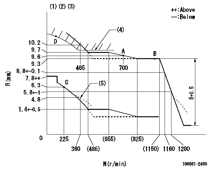
N:Pump speed
R:Rack position (mm)
(1)Lever ratio: RT
(2)Target shim dimension: TH
(3)Tolerance for racks not indicated: +-0.05mm.
(4)Excess fuel setting for starting: SXL
(5)Damper spring setting
----------
RT=1 TH=2.9mm SXL=9.8+-0.1mm
----------
----------
RT=1 TH=2.9mm SXL=9.8+-0.1mm
----------
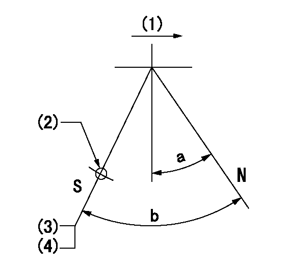
Speed control lever angle

F:Full speed
----------
----------
a=(13.5deg)+-5deg
----------
----------
a=(13.5deg)+-5deg
0000000901

F:Full load
I:Idle
(1)Stopper bolt setting
----------
----------
a=10deg+-5deg b=31deg+-3deg
----------
----------
a=10deg+-5deg b=31deg+-3deg
Stop lever angle
N:Pump normal
S:Stop the pump.
(1)Drive side
(2)Use the hole at R = aa
(3)Rack position bb
(4)Stopper bolt setting
----------
aa=32mm bb=3.5-0.5mm
----------
a=10.5deg+-5deg b=57.5deg+7deg-5deg
----------
aa=32mm bb=3.5-0.5mm
----------
a=10.5deg+-5deg b=57.5deg+7deg-5deg
0000001501 RACK SENSOR

V1:Supply voltage
V2f:Full side output voltage
V2i:Idle side output voltage
(A) Black
(B) Yellow
(C) Red
(D) Trimmer
(E): Shaft
(F) Nut
(G) Load lever
1. Load sensor adjustment
(1)Connect as shown in the above diagram and apply supply voltage V1.
(2)Hold the load lever (G) against the full side.
(3)Turn the shaft so that the voltage between (A) and (B) is V2.
(4)Hold the load lever (G) against the idle side.
(5)Adjust (D) so that the voltage between (A) and (B) is V2i.
(6)Repeat the above adjustments.
(7)Tighten the nut (F) at the point satisfying the standards.
(8)Hold the load lever against the full side stopper and the idle side stopper.
(9)At this time, confirm that the full side output voltage is V2f and the idle side output voltage is V2i.
----------
V1=5+-0.02V V2f=0.15+0.03V V2i=2.35-0.03V
----------
----------
V1=5+-0.02V V2f=0.15+0.03V V2i=2.35-0.03V
----------
Timing setting

(1)Pump vertical direction
(2)Coupling's key groove position at No 1 cylinder's beginning of injection
(3)-
(4)-
----------
----------
a=(40deg)
----------
----------
a=(40deg)
Information:
Electric Starting
Startability will be improved at temperatures below 16°C (60°F) by the use of a starting aid. A jacket water (coolant) heater or other means can be used to heat the crankcase oil.Start the engine using the following procedure:1. Perform all before-starting inspections.2. If the engine is equipped with a manual control, ensure that is in the RUN position. Place the transmission in NEUTRAL (and disengage the flywheel clutch, if equipped). For Generator Sets, open the main electrical circuit breaker.2. Move throttle to approximately half engine speed to get the fuel rack to move to the FUEL ON position.3. Turn the starter switch to START (or battery disconnect switch to the ON position) or the Engine Control Switch (ECS) to MAN. START. The starting motor will crank and attempt to start the engine. At temperatures below 0°C (32°F), it may be necessary to spray starting fluid into the air cleaner inlet. Additional injections of ether may be required to start and/or achieve low idle speed.
Excessive ether can cause piston and ring damage. When using starting fluid, follow the manufacturer's instructions carefully, use it sparingly and spray it ONLY WHILE CRANKING THE ENGINE. Failure to do so could result in an explosion and/or fire and possible personal injury.Use ether for cold starting purposes only.
Do not crank the engine for more than 30 seconds.
If a warm engine fails to start within 30 seconds: release the starter switch and wait two minutes to allow the starter motor to cool before using it again.4. As soon as the engine starts, allow the engine to idle for 3 to 5 minutes, or until the water temperature gauge indicator has begun to rise. The engine should run at low idle smoothly until speed is gradually increased to high idle.
Do not increase engine speed until the oil pressure gauge indicates normal. Oil pressure should rise within 15 seconds after the engine starts. If oil pressure is not indicated on gauge within 15 seconds, stop the engine, investigate and correct the cause.
5. Allow white smoke to clear up and proceed with normal operation. Do not apply load to the engine or increase engine speed until the oil pressure gauge indicates normal. Oil pressure should raise within 15 seconds after the engine starts. For starting in cold weather, to minimize white smoke: start the engine and allow the engine to idle for 30 seconds. Increase rpm until engine speed reaches 1200 rpm. Then allow the engine to return to low idle.6. Operate the engine at low load until all systems reach operating temperature. Check all gauges during the warm-up period.Engine Starting With Jumper Cables
When boost starting an engine, follow the instructions to properly start the engine. This engine is equipped with a 12 or 24 volt starting system. Use only equal voltage for boost starting. The use of higher voltage will damage the electrical system.
Batteries give off flammable fumes that can explode.Improper jumper cable connections can cause an explosion resulting in personal injury.Prevent sparks near the batteries.
Have questions with 106861-2480?
Group cross 106861-2480 ZEXEL
Mitsubishi
Mitsubishi
Mitsubishi
106861-2480
9 400 617 991
ME098599
INJECTION-PUMP ASSEMBLY
8DC9T
8DC9T