Information injection-pump assembly
BOSCH
9 400 617 990
9400617990
ZEXEL
106861-2470
1068612470
MITSUBISHI
ME098588
me098588
Rating:
Cross reference number
BOSCH
9 400 617 990
9400617990
ZEXEL
106861-2470
1068612470
MITSUBISHI
ME098588
me098588
Zexel num
Bosch num
Firm num
Name
106861-2470
9 400 617 990
ME098588 MITSUBISHI
INJECTION-PUMP ASSEMBLY
8DC9T * K 14CD INJECTION PUMP ASSY PE8P PE
8DC9T * K 14CD INJECTION PUMP ASSY PE8P PE
Calibration Data:
Adjustment conditions
Test oil
1404 Test oil ISO4113 or {SAEJ967d}
1404 Test oil ISO4113 or {SAEJ967d}
Test oil temperature
degC
40
40
45
Nozzle and nozzle holder
105780-8140
Bosch type code
EF8511/9A
Nozzle
105780-0000
Bosch type code
DN12SD12T
Nozzle holder
105780-2080
Bosch type code
EF8511/9
Opening pressure
MPa
17.2
Opening pressure
kgf/cm2
175
Injection pipe
Outer diameter - inner diameter - length (mm) mm 8-3-600
Outer diameter - inner diameter - length (mm) mm 8-3-600
Overflow valve
131424-4620
Overflow valve opening pressure
kPa
255
255
255
Overflow valve opening pressure
kgf/cm2
2.6
2.6
2.6
Tester oil delivery pressure
kPa
157
157
157
Tester oil delivery pressure
kgf/cm2
1.6
1.6
1.6
Direction of rotation (viewed from drive side)
Right R
Right R
Injection timing adjustment
Direction of rotation (viewed from drive side)
Right R
Right R
Injection order
1-2-7-3-
4-5-6-8
Pre-stroke
mm
4.8
4.75
4.85
Beginning of injection position
Governor side NO.1
Governor side NO.1
Difference between angles 1
Cyl.1-2 deg. 45 44.5 45.5
Cyl.1-2 deg. 45 44.5 45.5
Difference between angles 2
Cal 1-7 deg. 90 89.5 90.5
Cal 1-7 deg. 90 89.5 90.5
Difference between angles 3
Cal 1-3 deg. 135 134.5 135.5
Cal 1-3 deg. 135 134.5 135.5
Difference between angles 4
Cal 1-4 deg. 180 179.5 180.5
Cal 1-4 deg. 180 179.5 180.5
Difference between angles 5
Cal 1-5 deg. 225 224.5 225.5
Cal 1-5 deg. 225 224.5 225.5
Difference between angles 6
Cal 1-6 deg. 270 269.5 270.5
Cal 1-6 deg. 270 269.5 270.5
Difference between angles 7
Cal 1-8 deg. 315 314.5 315.5
Cal 1-8 deg. 315 314.5 315.5
Injection quantity adjustment
Adjusting point
A
Rack position
9.9
Pump speed
r/min
900
900
900
Average injection quantity
mm3/st.
146
143
149
Max. variation between cylinders
%
0
-3
3
Basic
*
Fixing the lever
*
Injection quantity adjustment_02
Adjusting point
B
Rack position
6.1+-0.5
Pump speed
r/min
275
275
275
Average injection quantity
mm3/st.
11.4
8.8
14
Max. variation between cylinders
%
0
-15
15
Fixing the rack
*
Timer adjustment
Pump speed
r/min
1100++
Advance angle
deg.
0
0
0
Remarks
Do not advance until starting N = 1100.
Do not advance until starting N = 1100.
Timer adjustment_02
Pump speed
r/min
-
Advance angle
deg.
3.5
3.5
3.5
Remarks
Measure the actual speed, stop
Measure the actual speed, stop
Test data Ex:
Governor adjustment
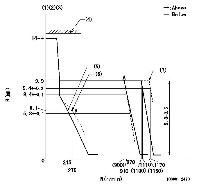
N:Pump speed
R:Rack position (mm)
(1)Target notch: K
(2)Tolerance for racks not indicated: +-0.05mm.
(3)Torque spring does not operate.
(4)RACK LIMIT not operating.
(5)Main spring setting
(6)Set idle sub-spring
(7)At delivery
----------
K=10
----------
----------
K=10
----------
Speed control lever angle
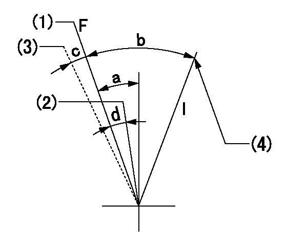
F:Full speed
I:Idle
(1)Pump speed = aa
(2)Pump speed = bb
(3)At delivery
(4)Stopper bolt setting
----------
aa=1110r/min bb=910r/min
----------
a=7deg+-5deg b=26deg+-5deg c=(2deg) d=6deg+-5deg
----------
aa=1110r/min bb=910r/min
----------
a=7deg+-5deg b=26deg+-5deg c=(2deg) d=6deg+-5deg
Stop lever angle

N:Pump normal
S:Stop the pump.
(1)Normal
----------
----------
a=19deg+-5deg b=46deg+-5deg
----------
----------
a=19deg+-5deg b=46deg+-5deg
Timing setting

(1)Pump vertical direction
(2)Coupling's key groove position at No 1 cylinder's beginning of injection
(3)-
(4)-
----------
----------
a=(40deg)
----------
----------
a=(40deg)
Information:
Emergency Stop Push Button
Emergency Stop Push Button (ESPB)The Emergency Stop Push Button (ESPB) requires resetting both the push button and the air inlet shutoff (if equipped) before the engine will start.
Always determine the cause of the engine shutdown. Make necessary repairs before attempting restarting the engine.Emergency shutoff controls are for EMERGENCY use ONLY. DO NOT use Emergency shutoff devices or controls for normal stopping procedure. Refer to the Engine Stopping section of this manual for normal stopping procedures.
Oil Pressure Switch
Typical example of oil pressure switches, mounted in the rear of the junction box.An oil pressure switch has wires connected to the electrical shutoff system for alarm or shutdown functions. The oil pressure switch senses oil pressure at the bearing oil gallery. Switches may close at 48 to 62 kPa (7 to 9 psi) below actual trip point. No resetting procedure is required.Water Temperature Contactor Switch
This contactor switch is a coolant temperature sensor.The water temperature contactor switch is located near the coolant water regulator housing. Excessive water temperature closes the switch. Maximum coolant temperature to trip shutoff is 104°C (219°F). The switch opens as the coolant cools. No resetting procedure is required. The unit has wires connected to the electrical shutoff system for alarm or shutdown functions.
The sensing element must be submerged in the coolant to operate. Be sure to have an adequate water supply in the jacket water system, or engine damage could result.
Coolant Loss Sensor (If Equipped)
The optional coolant loss sensor is usually mounted near the top of the engine expansion tank or radiator. The sensor detects when the coolant level is below a preset minimum level.
This coolant loss switch, shown next to a sight glass, is mounted on the side of a radiator.If the coolant level drops below the minimum level, the sensor may sound an alarm, or cause a shutdown to avoid engine overheating or possible engine damage. Coolant must be added to the radiator or expansion tank to clear or reset the condition. In the event of intermittent engine shutdowns, the coolant water level should be checked. Add premixed coolant water to the fill tank, to within 13 mm (1/2 inch) below the filler tube.Check the expansion tank or radiator daily for proper coolant level.Overspeed Shutoffs
The electrical shutoff for the overspeed switch uses a magnetic pickup mounted in the flywheel housing. The electrical shutoff works through the fuel shutoff solenoid and air inlet shutoff (if equipped).
Magnetic pickup (1), mounted in the flywheel housing (2).Should the engine overspeed, the magnetic pickup will sense the excess speed. If overspeed is sensed, the electrical shutoff closes the air and fuel shutoff solenoids (the fuel rack will move to fuel OFF position).The overspeed shutdown has to be reset. Reset the air inlet shutoff (if equipped) and the overspeed switch. Both switches are located in the junction box or control panel.
Overspeed Shutoff Switch (Electro-Mechanical)This switch is mounted either on the tachometer drive or the governor. Excessive engine speed closes the switch by centrifugal force.If equipped with a Caterpillar Generator
Have questions with 106861-2470?
Group cross 106861-2470 ZEXEL
Mitsubishi
Mitsubishi
Mitsubishi
106861-2470
9 400 617 990
ME098588
INJECTION-PUMP ASSEMBLY
8DC9T
8DC9T