Information injection-pump assembly
BOSCH
9 400 617 973
9400617973
ZEXEL
106861-2170
1068612170
MITSUBISHI
ME068083
me068083

Rating:
Cross reference number
BOSCH
9 400 617 973
9400617973
ZEXEL
106861-2170
1068612170
MITSUBISHI
ME068083
me068083
Zexel num
Bosch num
Firm num
Name
106861-2170
9 400 617 973
ME068083 MITSUBISHI
INJECTION-PUMP ASSEMBLY
8DC9T * K
8DC9T * K
Calibration Data:
Adjustment conditions
Test oil
1404 Test oil ISO4113 or {SAEJ967d}
1404 Test oil ISO4113 or {SAEJ967d}
Test oil temperature
degC
40
40
45
Nozzle and nozzle holder
105780-8140
Bosch type code
EF8511/9A
Nozzle
105780-0000
Bosch type code
DN12SD12T
Nozzle holder
105780-2080
Bosch type code
EF8511/9
Opening pressure
MPa
17.2
Opening pressure
kgf/cm2
175
Injection pipe
Outer diameter - inner diameter - length (mm) mm 8-3-600
Outer diameter - inner diameter - length (mm) mm 8-3-600
Overflow valve
131424-4620
Overflow valve opening pressure
kPa
255
221
289
Overflow valve opening pressure
kgf/cm2
2.6
2.25
2.95
Tester oil delivery pressure
kPa
157
157
157
Tester oil delivery pressure
kgf/cm2
1.6
1.6
1.6
Direction of rotation (viewed from drive side)
Right R
Right R
Injection timing adjustment
Direction of rotation (viewed from drive side)
Right R
Right R
Injection order
1-2-7-3-
4-5-6-8
Pre-stroke
mm
4.8
4.75
4.85
Beginning of injection position
Governor side NO.1
Governor side NO.1
Difference between angles 1
Cyl.1-2 deg. 45 44.5 45.5
Cyl.1-2 deg. 45 44.5 45.5
Difference between angles 2
Cal 1-7 deg. 90 89.5 90.5
Cal 1-7 deg. 90 89.5 90.5
Difference between angles 3
Cal 1-3 deg. 135 134.5 135.5
Cal 1-3 deg. 135 134.5 135.5
Difference between angles 4
Cal 1-4 deg. 180 179.5 180.5
Cal 1-4 deg. 180 179.5 180.5
Difference between angles 5
Cal 1-5 deg. 225 224.5 225.5
Cal 1-5 deg. 225 224.5 225.5
Difference between angles 6
Cal 1-6 deg. 270 269.5 270.5
Cal 1-6 deg. 270 269.5 270.5
Difference between angles 7
Cal 1-8 deg. 315 314.5 315.5
Cal 1-8 deg. 315 314.5 315.5
Injection quantity adjustment
Adjusting point
A
Rack position
11
Pump speed
r/min
850
850
850
Average injection quantity
mm3/st.
136.3
133.3
139.3
Max. variation between cylinders
%
0
-3
3
Basic
*
Fixing the lever
*
Injection quantity adjustment_02
Adjusting point
B
Rack position
10.4
Pump speed
r/min
900
900
900
Average injection quantity
mm3/st.
124
120
128
Max. variation between cylinders
%
0
-4
4
Fixing the lever
*
Injection quantity adjustment_03
Adjusting point
C
Rack position
5.3+-0.5
Pump speed
r/min
250
250
250
Average injection quantity
mm3/st.
18.5
15.9
21.1
Max. variation between cylinders
%
0
-15
15
Fixing the rack
*
Timer adjustment
Pump speed
r/min
900--
Advance angle
deg.
0
0
0
Remarks
Start
Start
Timer adjustment_02
Pump speed
r/min
850
Advance angle
deg.
0.5
Timer adjustment_03
Pump speed
r/min
900
Advance angle
deg.
0.8
Timer adjustment_04
Pump speed
r/min
-
Advance angle
deg.
3
2.5
3.5
Remarks
Measure the actual speed, stop
Measure the actual speed, stop
Test data Ex:
Governor adjustment
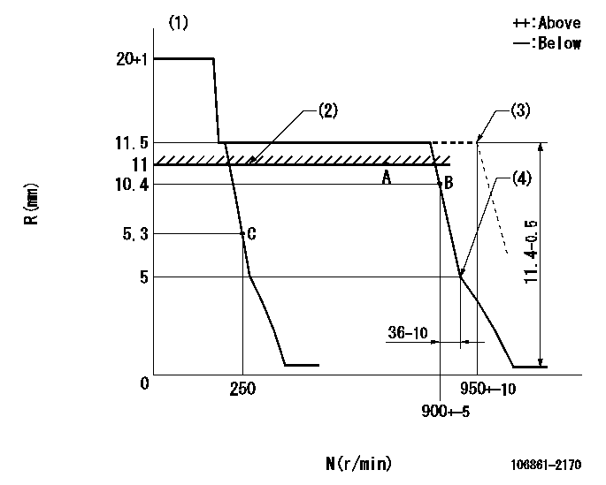
N:Pump speed
R:Rack position (mm)
(1)Target notch: K
(2)RACK LIMIT
(3)At shipping
(4)Idle sub spring setting: L1.
----------
K=10 L1=5-0.5mm
----------
----------
K=10 L1=5-0.5mm
----------
Speed control lever angle

F:Full speed
I:Idle
(1)Stopper bolt setting
(2)At shipping
----------
----------
a=3deg+-5deg b=27deg+-5deg c=(2deg)
----------
----------
a=3deg+-5deg b=27deg+-5deg c=(2deg)
Stop lever angle

N:Pump normal
S:Stop the pump.
(1)At shipping
----------
----------
a=19deg+-5deg b=46deg+-5deg
----------
----------
a=19deg+-5deg b=46deg+-5deg
Timing setting

(1)Pump vertical direction
(2)Coupling's key groove position at No 1 cylinder's beginning of injection
(3)-
(4)-
----------
----------
a=(40deg)
----------
----------
a=(40deg)
Information:
Rework Procedure
Replacement of Diesel Oxidation Catalyst (DOC):
1. Remove three 222-8823 Bolts and three 232-3209 Washers to separate the 360-8875 Bellows Tube Assembly from the 360-8849 Catalytic Converter Group. Refer to Image1.1.1.
Image1.1.1
2. Loosen the clamp. Remove the DOC from the Catalytic Converter Group. Refer to Images1.2.1 and 1.2.2.
Image1.2.1
Image1.2.2
3. Remove the ring from the DOC. Remove the clamp from the catalytic converter. Refer to Images1.3.1 and 1.3.2.
Image1.3.1
Image1.3.2
4. Remove the five screws and five washers from the insulation around the DOC. Remove the insulation from the DOC. The insulation will be reused. Refer to Images1.4.1 and 1.4.2.
Image1.4.1
Image1.4.2
5. Install the insulation that was removed from the old DOC on to the new DOC. Refer to Image1.5.1.
Image1.5.1
6. Clean the sealing surface of the DOC flange. Clean the sealing surface of the flange on the catalytic converter group. Clean the ring that was removed from the old DOC. Refer to Images1.6.1, 1.6.2, and 1.6.3.
Image1.6.1
Image1.6.2
Image1.6.3
7. Apply seal paste to both sides of the ring, to the flange surfaces of the new DOC, and the catalytic converter. Refer to Image1.7.1.
Note: Make sure to cover the complete ring and flange surfaces with seal paste when applying it.
Image1.7.1
8. Place the ring on the flange of the new DOC. Position the new DOC against the catalytic converter. Refer to Images1.8.1 and 1.8.2.
Image1.8.1
Image1.8.2
9. Orient the DOC so that it will line up correctly with the bellows tube. Install and orient the clamp in order to hold the new DOC in place. Apply sealing paste or high temperature grease to the bolt of the clamp. Tighten the clamp. Then reattach the DOC to the bellows tube. Refer to Image1.9.1.
Image1.9.1
10. Tap the clamp around the circumference to properly seat the clamp. Tighten the clamp to a specified torque of 18 N.m (13.3 ft-lb). Apply sealing paste or high temperature grease to the three 222-8823 Bolts to assemble the bellows. Refer to Image1.10.1.
Image1.10.1
11. Write down the number of active regenerations. This number can be found in the Monitor Service Menu in the Aftertreatment Status section. Enter this information to the claim story when you submit your claim. Refer to Image1.11.1.
Image1.11.1
Have questions with 106861-2170?
Group cross 106861-2170 ZEXEL
Mitsubishi
106861-2170
9 400 617 973
ME068083
INJECTION-PUMP ASSEMBLY
8DC9T
8DC9T