Information injection-pump assembly
ZEXEL
106861-2160
1068612160

Rating:
Cross reference number
ZEXEL
106861-2160
1068612160
Zexel num
Bosch num
Firm num
Name
Calibration Data:
Adjustment conditions
Test oil
1404 Test oil ISO4113 or {SAEJ967d}
1404 Test oil ISO4113 or {SAEJ967d}
Test oil temperature
degC
40
40
45
Nozzle and nozzle holder
105780-8140
Bosch type code
EF8511/9A
Nozzle
105780-0000
Bosch type code
DN12SD12T
Nozzle holder
105780-2080
Bosch type code
EF8511/9
Opening pressure
MPa
17.2
Opening pressure
kgf/cm2
175
Injection pipe
Outer diameter - inner diameter - length (mm) mm 8-3-600
Outer diameter - inner diameter - length (mm) mm 8-3-600
Overflow valve
131424-4620
Overflow valve opening pressure
kPa
255
221
289
Overflow valve opening pressure
kgf/cm2
2.6
2.25
2.95
Tester oil delivery pressure
kPa
157
157
157
Tester oil delivery pressure
kgf/cm2
1.6
1.6
1.6
Direction of rotation (viewed from drive side)
Right R
Right R
Injection timing adjustment
Direction of rotation (viewed from drive side)
Right R
Right R
Injection order
1-2-7-3-
4-5-6-8
Pre-stroke
mm
4.8
4.75
4.85
Beginning of injection position
Governor side NO.1
Governor side NO.1
Difference between angles 1
Cyl.1-2 deg. 45 44.5 45.5
Cyl.1-2 deg. 45 44.5 45.5
Difference between angles 2
Cal 1-7 deg. 90 89.5 90.5
Cal 1-7 deg. 90 89.5 90.5
Difference between angles 3
Cal 1-3 deg. 135 134.5 135.5
Cal 1-3 deg. 135 134.5 135.5
Difference between angles 4
Cal 1-4 deg. 180 179.5 180.5
Cal 1-4 deg. 180 179.5 180.5
Difference between angles 5
Cal 1-5 deg. 225 224.5 225.5
Cal 1-5 deg. 225 224.5 225.5
Difference between angles 6
Cal 1-6 deg. 270 269.5 270.5
Cal 1-6 deg. 270 269.5 270.5
Difference between angles 7
Cal 1-8 deg. 315 314.5 315.5
Cal 1-8 deg. 315 314.5 315.5
Injection quantity adjustment
Adjusting point
-
Rack position
11.4
Pump speed
r/min
700
700
700
Each cylinder's injection qty
mm3/st.
140
135.8
144.2
Basic
*
Fixing the rack
*
Standard for adjustment of the maximum variation between cylinders
*
Injection quantity adjustment_02
Adjusting point
C
Rack position
7+-0.5
Pump speed
r/min
225
225
225
Each cylinder's injection qty
mm3/st.
18.5
16
21
Fixing the rack
*
Standard for adjustment of the maximum variation between cylinders
*
Injection quantity adjustment_03
Adjusting point
A
Rack position
R1(11.4)
Pump speed
r/min
700
700
700
Average injection quantity
mm3/st.
140
139
141
Basic
*
Fixing the lever
*
Boost pressure
kPa
49.3
49.3
Boost pressure
mmHg
370
370
Injection quantity adjustment_04
Adjusting point
B
Rack position
R1(11.4)
Pump speed
r/min
1100
1100
1100
Average injection quantity
mm3/st.
139
132.6
145.4
Difference in delivery
mm3/st.
12.8
12.8
12.8
Fixing the lever
*
Boost pressure
kPa
49.3
49.3
Boost pressure
mmHg
370
370
Injection quantity adjustment_05
Adjusting point
D
Rack position
11.2
Pump speed
r/min
400
400
400
Average injection quantity
mm3/st.
128.5
124.8
132.2
Fixing the lever
*
Boost pressure
kPa
18.7
18.7
18.7
Boost pressure
mmHg
140
140
140
Injection quantity adjustment_06
Adjusting point
E
Rack position
-
Pump speed
r/min
200
200
200
Average injection quantity
mm3/st.
130
110
150
Fixing the lever
*
Boost pressure
kPa
0
0
0
Boost pressure
mmHg
0
0
0
Boost compensator adjustment
Pump speed
r/min
400
400
400
Rack position
9.9
Boost pressure
kPa
4
4
4
Boost pressure
mmHg
30
30
30
Boost compensator adjustment_02
Pump speed
r/min
400
400
400
Rack position
11.2
Boost pressure
kPa
18.7
17.4
20
Boost pressure
mmHg
140
130
150
Boost compensator adjustment_03
Pump speed
r/min
400
400
400
Rack position
(12.5)
Boost pressure
kPa
35.3
28.6
42
Boost pressure
mmHg
265
215
315
Timer adjustment
Pump speed
r/min
980--
Advance angle
deg.
0
0
0
Remarks
Start
Start
Timer adjustment_02
Pump speed
r/min
930
Advance angle
deg.
0.5
Timer adjustment_03
Pump speed
r/min
1050
Advance angle
deg.
2
1.5
2.5
Timer adjustment_04
Pump speed
r/min
1100
Advance angle
deg.
4
3.5
4.5
Remarks
Finish
Finish
Test data Ex:
Governor adjustment
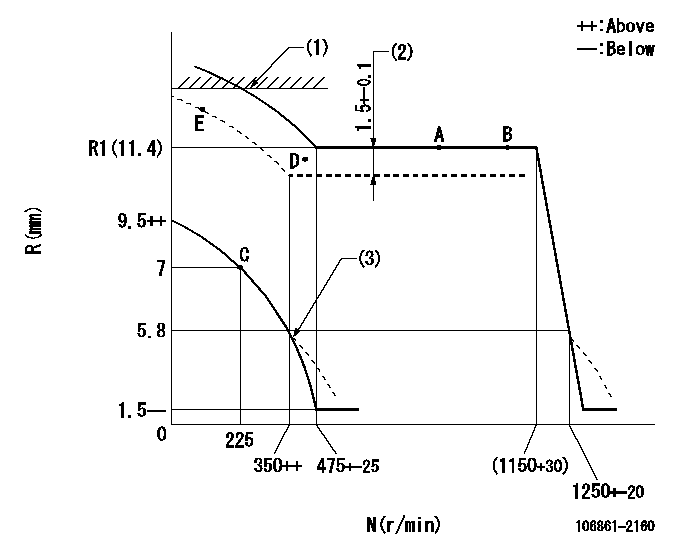
N:Pump speed
R:Rack position (mm)
(1)Rack limit using stop lever: RA
(2)Boost compensator stroke
(3)Beginning of damper spring operation: DL
----------
RA=13+0.5mm DL=5.8-0.2mm
----------
----------
RA=13+0.5mm DL=5.8-0.2mm
----------
0000000901

F:Full load
I:Idle
(1)Stopper bolt setting
----------
----------
a=14deg+-5deg b=20deg+-3deg
----------
----------
a=14deg+-5deg b=20deg+-3deg
Stop lever angle
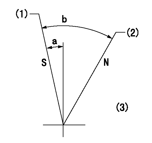
N:Pump normal
S:Stop the pump.
(1)Rack position = aa, stopper bolt setting
(2)Rack position bb
(3)Using reverse lever
----------
aa=4.7-0.5mm bb=13+0.5mm
----------
a=3deg+-6deg b=37deg+-6deg
----------
aa=4.7-0.5mm bb=13+0.5mm
----------
a=3deg+-6deg b=37deg+-6deg
0000001501 MICRO SWITCH
Adjustment of the micro-switch
Adjust the bolt to obtain the following lever position when the micro-switch is ON.
(1)Speed N1
(2)Rack position Ra
----------
N1=325+-5r/min Ra=6.7mm
----------
----------
N1=325+-5r/min Ra=6.7mm
----------
Timing setting

(1)Pump vertical direction
(2)Coupling's key groove position at No 1 cylinder's beginning of injection
(3)-
(4)-
----------
----------
a=(40deg)
----------
----------
a=(40deg)
Information:
(1) Bore in idler gear bearing ... 28.600 0.061 mm (1.1260 .0024 in) Diameter of idler gear shaft ... 28.512 0.013 mm (1.1225 .0005 in)Clearance between bearing and shaft ... .014 to .162 mm (.0011 to .0059 in)(2) Clearance between gear and body of pump ... 0.05 to 0.66 mm (.002 to .026 in)(3) Diameter of shafts for pump ... 22.217 0.005 mm (.8747 .0002 in) Bore in bearings for shafts ... 22.286 0.051 mm (.8774 .0020 in)Clearance between shafts and bearings ... .013 to .125 mm (.0010 to .0050 in)(4) Depth that bearings are installed in pump bodies ... 1.52 0.25 mm (.060 .010 in)(5) Length of gears ... 50.808 0.025 mm (2.0003 0.0010 in) Depth of bore in pump body for gears ... 50.935 0.020 mm (2.0053 0.0008 in)Clearance between end of gears and pump body ... 0.081 to 0.173 mm (.0032 to .0068 in)(6) Length of gears ... 38.070 0.025 mm (1.4988 0.0010 in) Depth of bore in pump body for gears ... 38.197 0.020 mm (1.5038 0.0008 in)Clearance between end of gears and pump body ... 0.081 to 0.173 mm (.0032 to .0068 in)(7) Distance from the end of the idler shafts to gear faces ... 21.03 0.13 mm (.828 .005 in) Maximum temperature of gear when shrinking in place ... 400°C (750°F)(8) Distance from the end of the drive shaft to gear face ... 38.23 0.13 mm (1.505 0.005 in) Maximum temperature of gear when shrinking in place ... 400°C (750°F)(9) Torque for bolt holding drive gear to drive shaft ... 47 9 N m (35 7 lb ft) Install the bearings in the cover and body for the oil pump so the bearing junctions (joints) are in the position shown.(10) Distance dowel extends from body ... 4.1 0.5 mm (.16 .02 in)(11) Shaft assembly. Distance shaft assembly extends from body ... 30.50 0.25 mm (1.201 0.010 in)
Section A-A
Oil Pump Bypass Spring(12) 115-7545 Spring: Length under test force ... 22.22 mm (.875 in)Test force ... 780 N (175 lb)Free length after test ... 25.4 mm (1.00 in)Outside diameter ... 18.54 mm (.730 in) Before running, lubricate pump with oil. Pump must rotate freely by hand.
Section A-A
Oil Pump Bypass Spring(12) 115-7545 Spring: Length under test force ... 22.22 mm (.875 in)Test force ... 780 N (175 lb)Free length after test ... 25.4 mm (1.00 in)Outside diameter ... 18.54 mm (.730 in) Before running, lubricate pump with oil. Pump must rotate freely by hand.