Information injection-pump assembly
BOSCH
9 400 610 131
9400610131
ZEXEL
106861-2141
1068612141
MITSUBISHI
ME098501
me098501
Rating:
Service parts 106861-2141 INJECTION-PUMP ASSEMBLY:
1.
_
7.
COUPLING PLATE
8.
_
9.
_
11.
Nozzle and Holder
ME066034
12.
Open Pre:MPa(Kqf/cm2)
21.6{220}

15.
NOZZLE SET
Include in #1:
106861-2141
as INJECTION-PUMP ASSEMBLY
Cross reference number
BOSCH
9 400 610 131
9400610131
ZEXEL
106861-2141
1068612141
MITSUBISHI
ME098501
me098501
Zexel num
Bosch num
Firm num
Name
106861-2141
9 400 610 131
ME098501 MITSUBISHI
INJECTION-PUMP ASSEMBLY
8DC90PT * K 14CD INJECTION PUMP ASSY PE8P PE
8DC90PT * K 14CD INJECTION PUMP ASSY PE8P PE
Calibration Data:
Adjustment conditions
Test oil
1404 Test oil ISO4113 or {SAEJ967d}
1404 Test oil ISO4113 or {SAEJ967d}
Test oil temperature
degC
40
40
45
Nozzle and nozzle holder
105780-8140
Bosch type code
EF8511/9A
Nozzle
105780-0000
Bosch type code
DN12SD12T
Nozzle holder
105780-2080
Bosch type code
EF8511/9
Opening pressure
MPa
17.2
Opening pressure
kgf/cm2
175
Injection pipe
Outer diameter - inner diameter - length (mm) mm 8-3-600
Outer diameter - inner diameter - length (mm) mm 8-3-600
Overflow valve
131424-4620
Overflow valve opening pressure
kPa
255
221
289
Overflow valve opening pressure
kgf/cm2
2.6
2.25
2.95
Tester oil delivery pressure
kPa
157
157
157
Tester oil delivery pressure
kgf/cm2
1.6
1.6
1.6
Direction of rotation (viewed from drive side)
Right R
Right R
Injection timing adjustment
Direction of rotation (viewed from drive side)
Right R
Right R
Injection order
1-2-7-3-
4-5-6-8
Pre-stroke
mm
4.8
4.75
4.85
Beginning of injection position
Governor side NO.1
Governor side NO.1
Difference between angles 1
Cyl.1-2 deg. 45 44.5 45.5
Cyl.1-2 deg. 45 44.5 45.5
Difference between angles 2
Cal 1-7 deg. 90 89.5 90.5
Cal 1-7 deg. 90 89.5 90.5
Difference between angles 3
Cal 1-3 deg. 135 134.5 135.5
Cal 1-3 deg. 135 134.5 135.5
Difference between angles 4
Cal 1-4 deg. 180 179.5 180.5
Cal 1-4 deg. 180 179.5 180.5
Difference between angles 5
Cal 1-5 deg. 225 224.5 225.5
Cal 1-5 deg. 225 224.5 225.5
Difference between angles 6
Cal 1-6 deg. 270 269.5 270.5
Cal 1-6 deg. 270 269.5 270.5
Difference between angles 7
Cal 1-8 deg. 315 314.5 315.5
Cal 1-8 deg. 315 314.5 315.5
Injection quantity adjustment
Adjusting point
A
Rack position
11
Pump speed
r/min
850
850
850
Average injection quantity
mm3/st.
136.3
133.3
139.3
Max. variation between cylinders
%
0
-3
3
Basic
*
Fixing the lever
*
Injection quantity adjustment_02
Adjusting point
B
Rack position
10.4
Pump speed
r/min
900
900
900
Average injection quantity
mm3/st.
124
120
128
Max. variation between cylinders
%
0
-4
4
Fixing the lever
*
Injection quantity adjustment_03
Adjusting point
C
Rack position
5.3+-0.5
Pump speed
r/min
250
250
250
Average injection quantity
mm3/st.
18.5
15.9
21.1
Max. variation between cylinders
%
0
-15
15
Fixing the rack
*
Timer adjustment
Pump speed
r/min
900--
Advance angle
deg.
0
0
0
Remarks
Start
Start
Timer adjustment_02
Pump speed
r/min
850
Advance angle
deg.
0.5
Timer adjustment_03
Pump speed
r/min
900
Advance angle
deg.
0.8
Timer adjustment_04
Pump speed
r/min
-
Advance angle
deg.
3
2.5
3.5
Remarks
Measure the actual speed, stop
Measure the actual speed, stop
Test data Ex:
Governor adjustment
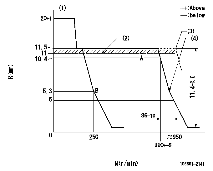
N:Pump speed
R:Rack position (mm)
(1)Target notch: K
(2)RACK LIMIT
(3)Setting at shipping
(4)Idle sub spring setting: L1.
----------
K=10 L1=5-0.5mm
----------
----------
K=10 L1=5-0.5mm
----------
Speed control lever angle
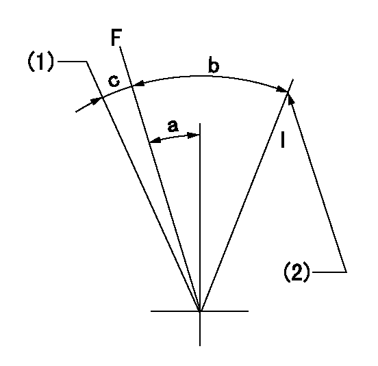
F:Full speed
I:Idle
(1)At shipping
(2)Stopper bolt setting
----------
----------
a=3deg+-5deg b=27deg+-5deg c=(2deg)
----------
----------
a=3deg+-5deg b=27deg+-5deg c=(2deg)
Stop lever angle

N:Pump normal
S:Stop the pump.
(1)At shipping
----------
----------
a=19deg+-5deg b=46deg+-5deg
----------
----------
a=19deg+-5deg b=46deg+-5deg
Timing setting

(1)Pump vertical direction
(2)Coupling's key groove position at No 1 cylinder's beginning of injection
(3)-
(4)-
----------
----------
a=(40deg)
----------
----------
a=(40deg)
Information:
PARTS NEEDED
Qty
Part Number Description
1 4609257 INJECTOR AS-DEF
1 5398400 SFWR GP-A1000
1 BULK_COOLANT COOLANT (MAX 1 GALLON)
In order to allow equitable parts availability to all participating dealers, please limit your initial parts order to not exceed 2% of dealership population. This is an initial order recommendation only, and the ultimate responsibility for ordering the total number of parts needed to satisfy the program lies with the dealer.
ACTION REQUIRED
Ensure that all safety information, warnings, and instructions are read and understood before any operation or any maintenance procedures are performed. Refer to the Operation and Maintenance Manual "Safety Section".
1. Remove the existing DEF injector assembly and replace with a new 460-9257 DEF Injector Assembly. Refer to UENR4468, Disassembly and Assembly, to remove and install the new DEF Injector Assembly.
2. Update the engine software. Reflash the engine controller (ECM) with the 539-8400 Software Group or latest available on SIS Web.
SERVICE CLAIM ALLOWANCES
Product smu/age whichever comes first Caterpillar Dealer Suggested Customer Suggested
Parts % Labor Hrs% Parts % Labor Hrs% Parts % Labor Hrs%
0-3000 hrs,
0-36 mo 100.0% 100.0% 0.0% 0.0% 0.0% 0.0%
3001-5000 hrs,
37-60 mo 100.0% 0.0% 0.0% 0.0% 0.0% 100.0%
This is a 2.0-hour job
PARTS DISPOSITION
Handle the parts in accordance with your Warranty Bulletin on warranty parts handling.
Have questions with 106861-2141?
Group cross 106861-2141 ZEXEL
Mitsubishi
106861-2141
9 400 610 131
ME098501
INJECTION-PUMP ASSEMBLY
8DC90PT
8DC90PT