Information injection-pump assembly
ZEXEL
106861-2060
1068612060
Rating:
Service parts 106861-2060 INJECTION-PUMP ASSEMBLY:
1.
_
7.
COUPLING PLATE
8.
_
9.
_
11.
Nozzle and Holder
ME066034
12.
Open Pre:MPa(Kqf/cm2)
21.6{220}

15.
NOZZLE SET
Include in #1:
106861-2060
as INJECTION-PUMP ASSEMBLY
Cross reference number
ZEXEL
106861-2060
1068612060
Zexel num
Bosch num
Firm num
Name
Calibration Data:
Adjustment conditions
Test oil
1404 Test oil ISO4113 or {SAEJ967d}
1404 Test oil ISO4113 or {SAEJ967d}
Test oil temperature
degC
40
40
45
Nozzle and nozzle holder
105780-8140
Bosch type code
EF8511/9A
Nozzle
105780-0000
Bosch type code
DN12SD12T
Nozzle holder
105780-2080
Bosch type code
EF8511/9
Opening pressure
MPa
17.2
Opening pressure
kgf/cm2
175
Injection pipe
Outer diameter - inner diameter - length (mm) mm 8-3-600
Outer diameter - inner diameter - length (mm) mm 8-3-600
Overflow valve opening pressure
kPa
255
221
289
Overflow valve opening pressure
kgf/cm2
2.6
2.25
2.95
Tester oil delivery pressure
kPa
157
157
157
Tester oil delivery pressure
kgf/cm2
1.6
1.6
1.6
Direction of rotation (viewed from drive side)
Right R
Right R
Injection timing adjustment
Direction of rotation (viewed from drive side)
Right R
Right R
Injection order
1-2-7-3-
4-5-6-8
Pre-stroke
mm
4.8
4.75
4.85
Beginning of injection position
Governor side NO.1
Governor side NO.1
Difference between angles 1
Cyl.1-2 deg. 45 44.5 45.5
Cyl.1-2 deg. 45 44.5 45.5
Difference between angles 2
Cal 1-7 deg. 90 89.5 90.5
Cal 1-7 deg. 90 89.5 90.5
Difference between angles 3
Cal 1-3 deg. 135 134.5 135.5
Cal 1-3 deg. 135 134.5 135.5
Difference between angles 4
Cal 1-4 deg. 180 179.5 180.5
Cal 1-4 deg. 180 179.5 180.5
Difference between angles 5
Cal 1-5 deg. 225 224.5 225.5
Cal 1-5 deg. 225 224.5 225.5
Difference between angles 6
Cal 1-6 deg. 270 269.5 270.5
Cal 1-6 deg. 270 269.5 270.5
Difference between angles 7
Cal 1-8 deg. 315 314.5 315.5
Cal 1-8 deg. 315 314.5 315.5
Injection quantity adjustment
Adjusting point
-
Rack position
9.2
Pump speed
r/min
700
700
700
Each cylinder's injection qty
mm3/st.
134
130
138
Basic
*
Fixing the rack
*
Standard for adjustment of the maximum variation between cylinders
*
Injection quantity adjustment_02
Adjusting point
D
Rack position
6.2+-0.5
Pump speed
r/min
200
200
200
Each cylinder's injection qty
mm3/st.
18.5
15.7
21.3
Fixing the rack
*
Standard for adjustment of the maximum variation between cylinders
*
Injection quantity adjustment_03
Adjusting point
A
Rack position
R1(9.2)
Pump speed
r/min
700
700
700
Average injection quantity
mm3/st.
134
133
135
Fixing the lever
*
Boost pressure
kPa
40
40
Boost pressure
mmHg
300
300
Injection quantity adjustment_04
Adjusting point
B
Rack position
R1(9.2)
Pump speed
r/min
1100
1100
1100
Average injection quantity
mm3/st.
141
135.4
146.6
Difference in delivery
mm3/st.
11.2
11.2
11.2
Fixing the lever
*
Boost pressure
kPa
40
40
Boost pressure
mmHg
300
300
Injection quantity adjustment_05
Adjusting point
C
Rack position
R2(8.9)
Pump speed
r/min
500
500
500
Average injection quantity
mm3/st.
120
116
124
Fixing the lever
*
Boost pressure
kPa
0
0
0
Boost pressure
mmHg
0
0
0
Injection quantity adjustment_06
Adjusting point
E
Rack position
9.9+-0.5
Pump speed
r/min
100
100
100
Average injection quantity
mm3/st.
110
90
130
Fixing the lever
*
Boost pressure
kPa
0
0
0
Boost pressure
mmHg
0
0
0
Boost compensator adjustment
Pump speed
r/min
600
600
600
Rack position
R2(8.9)
Boost pressure
kPa
22
20.7
23.3
Boost pressure
mmHg
165
155
175
Boost compensator adjustment_02
Pump speed
r/min
600
600
600
Rack position
R1(9.2)
Boost pressure
kPa
31.3
24.6
38
Boost pressure
mmHg
235
185
285
Timer adjustment
Pump speed
r/min
850+-50
Advance angle
deg.
0
0
0
Remarks
Start
Start
Timer adjustment_02
Pump speed
r/min
900
Advance angle
deg.
0.9
0.4
1.4
Timer adjustment_03
Pump speed
r/min
1000
Advance angle
deg.
2.3
1.8
2.8
Timer adjustment_04
Pump speed
r/min
1150
Advance angle
deg.
5.5
5
6
Remarks
Finish
Finish
Test data Ex:
Governor adjustment
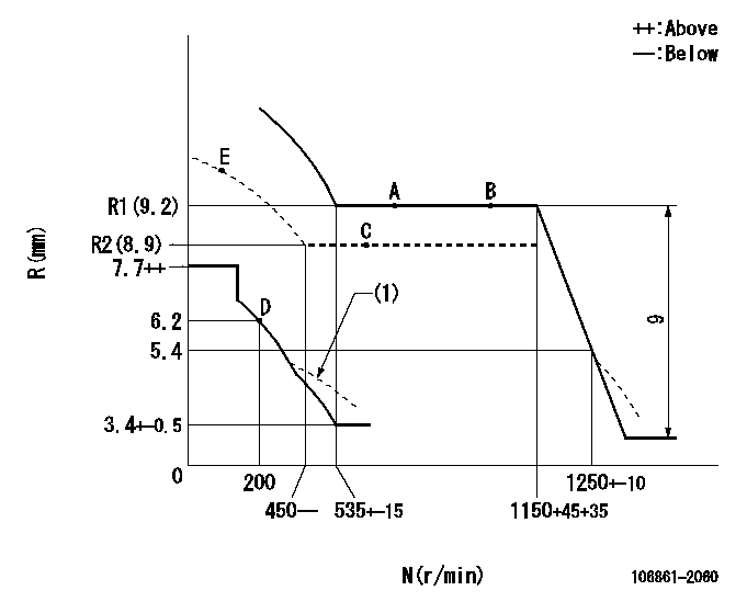
N:Pump speed
R:Rack position (mm)
(1)Damper spring setting: DL
----------
DL=5.4-0.2mm
----------
----------
DL=5.4-0.2mm
----------
Speed control lever angle

F:Full speed
----------
----------
a=18deg+-5deg
----------
----------
a=18deg+-5deg
0000000901

F:Full load
I:Idle
(1)Stopper bolt setting
----------
----------
a=10deg+-5deg b=21.5deg+-3deg
----------
----------
a=10deg+-5deg b=21.5deg+-3deg
Stop lever angle
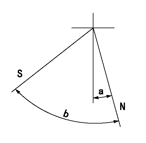
N:Pump normal
S:Stop the pump.
----------
----------
a=10deg+-5deg b=64deg+-5deg
----------
----------
a=10deg+-5deg b=64deg+-5deg
0000001501 MICRO SWITCH
Adjustment of the micro-switch
Adjust the bolt to obtain the following lever position when the micro-switch is ON.
(1)Speed N1
(2)Rack position Ra
----------
N1=325+-5r/min Ra=5.9mm
----------
----------
N1=325+-5r/min Ra=5.9mm
----------
0000001601 RACK SENSOR

V1:Supply voltage
V2f:Full side output voltage
V2i:Idle side output voltage
(A) Black
(B) Yellow
(C) Red
(D) Trimmer
(E): Shaft
(F) Nut
(G) Load lever
1. Load sensor adjustment
(1)Connect as shown in the above diagram and apply supply voltage V1.
(2)Hold the load lever (G) against the full side.
(3)Turn the shaft so that the voltage between (A) and (B) is V2.
(4)Hold the load lever (G) against the idle side.
(5)Adjust (D) so that the voltage between (A) and (B) is V2i.
(6)Repeat the above adjustments.
(7)Tighten the nut (F) at the point satisfying the standards.
(8)Hold the load lever against the full side stopper and the idle side stopper.
(9)At this time, confirm that the full side output voltage is V2f and the idle side output voltage is V2i.
----------
V1=5+-0.02V V2f=0.15+-0.03V V2i=2.35-0.03V
----------
----------
V1=5+-0.02V V2f=0.15+-0.03V V2i=2.35-0.03V
----------
Information:
New Indicator Lamps On Console
Illustration 28.Three lamps are now located on the right side of a cover above the dash. See Illustration 28. These lamps are used to alert the operator to various engine conditions.* Engine Fault And Diagnostic Lamp (B) - This lamp indicates the presence of any engine faults logged in the ECM. The lamp will light when an engine fault occurs and remain lighted until the problem causing the fault indication has been corrected. To assist in diagnosing problems the fault type will be displayed in a coded manner when the panel test switch is in the DOWN position. See the appropriate Service Manuals for code descriptions.* Air Cleaner Restriction Lamp (C) - When lit, this lamp indicates the air cleaners are in need of servicing. * Engine Overspeed Lamp (D) - When the engine speed exceeds 2100 rpm, this lamp will light. This will alert the operator to take steps to limit engine speed. If the engine speed continues to increase above 2300 rpm, the lamp will flash on and off. This will alert the operator to take steps to reduce engine speed. When the engine speed is reduced below 2000 rpm the lamp will turn off.EMS Panel and Diagnostic Check Switch
Illustration 29.The panel test switch (E) located on the dash below the EMS panel now has two functions. It will continue to test the EMS panel when in the UP position. When the knob is in the DOWN position it will activate the engine self-diagnostic system by lighting the check engine lamp. This is the red lamp located in the left position in the cover above the dash. When activated this lamp will flash out a system of codes which will identify any active faults. See Illustration 29.If there are no active faults the lamp will flash a code "55" by lighting five times, pausing briefly, and lighting five times again. If the light flashes other codes, refer to the troubleshooting guide.Starting Aid System
Place starting aid system switch (F) in the AUT (down) position before starting the engine. - When temperatures require ether as an aid for starting, a metered amount of ether is injected. If the engine runs rough, move the toggle switch up to the MANUAL position, and additional ether will be injected in metered doses until the engine runs smoothly.When the engine runs smoothly, return the switch to the OFF (centered) position. See Illustration 29. Place the starting aid switch in the OFF position, when using the "Crank without injection" diagnostic feature of the ECM. This will prevent ether injection into the engine during the troubleshooting procedure.Machine Checkout and Test
When the engine installation is complete, refill, and/or check the fluid levels in all compartments of the machine. Before starting the engine, visually inspect the machine for any fluid leaks, loose or missing fasteners, fittings or wires. Correct any discrepancies which may be present before cranking or starting the engine.The engine being installed has been tested. However, be prepared for an