Information injection-pump assembly
ZEXEL
106861-1434
1068611434
ISUZU
1156022433
1156022433
Rating:
Service parts 106861-1434 INJECTION-PUMP ASSEMBLY:
1.
_
6.
COUPLING PLATE
7.
COUPLING PLATE
8.
_
9.
_
11.
Nozzle and Holder
1-15300-163-2
12.
Open Pre:MPa(Kqf/cm2)
15.7{160}/22.1{225}
15.
NOZZLE SET
Include in #1:
106861-1434
as INJECTION-PUMP ASSEMBLY
Cross reference number
ZEXEL
106861-1434
1068611434
ISUZU
1156022433
1156022433
Zexel num
Bosch num
Firm num
Name
Calibration Data:
Adjustment conditions
Test oil
1404 Test oil ISO4113 or {SAEJ967d}
1404 Test oil ISO4113 or {SAEJ967d}
Test oil temperature
degC
40
40
45
Nozzle and nozzle holder
105780-8140
Bosch type code
EF8511/9A
Nozzle
105780-0000
Bosch type code
DN12SD12T
Nozzle holder
105780-2080
Bosch type code
EF8511/9
Opening pressure
MPa
17.2
Opening pressure
kgf/cm2
175
Injection pipe
Outer diameter - inner diameter - length (mm) mm 8-3-600
Outer diameter - inner diameter - length (mm) mm 8-3-600
Overflow valve (drive side)
134424-3720
Overflow valve opening pressure (drive side)
kPa
255
221
289
Overflow valve opening pressure (drive side)
kgf/cm2
2.6
2.25
2.95
Overflow valve (governor side)
134424-2720
Overflow valve opening pressure (governor side)
kPa
255
221
289
Overflow valve opening pressure (governor side)
kgf/cm2
2.6
2.25
2.95
Tester oil delivery pressure
kPa
157
157
157
Tester oil delivery pressure
kgf/cm2
1.6
1.6
1.6
Direction of rotation (viewed from drive side)
Right R
Right R
Injection timing adjustment
Direction of rotation (viewed from drive side)
Right R
Right R
Injection order
1-8-7-3-
6-5-4-2
Pre-stroke
mm
4
3.97
4.03
Beginning of injection position
Governor side NO.1
Governor side NO.1
Difference between angles 1
Cal 1-8 deg. 45 44.75 45.25
Cal 1-8 deg. 45 44.75 45.25
Difference between angles 2
Cal 1-7 deg. 90 89.75 90.25
Cal 1-7 deg. 90 89.75 90.25
Difference between angles 3
Cal 1-3 deg. 135 134.75 135.25
Cal 1-3 deg. 135 134.75 135.25
Difference between angles 4
Cal 1-6 deg. 180 179.75 180.25
Cal 1-6 deg. 180 179.75 180.25
Difference between angles 5
Cal 1-5 deg. 225 224.75 225.25
Cal 1-5 deg. 225 224.75 225.25
Difference between angles 6
Cal 1-4 deg. 270 269.75 270.25
Cal 1-4 deg. 270 269.75 270.25
Difference between angles 7
Cyl.1-2 deg. 315 314.75 315.25
Cyl.1-2 deg. 315 314.75 315.25
Injection quantity adjustment
Adjusting point
B
Rack position
6.6
Pump speed
r/min
700
700
700
Average injection quantity
mm3/st.
75.5
74
77
Max. variation between cylinders
%
0
-2
2
Basic
*
Fixing the lever
*
Injection quantity adjustment_02
Adjusting point
D
Rack position
4.9+-0.5
Pump speed
r/min
225
225
225
Average injection quantity
mm3/st.
8
6.6
9.4
Max. variation between cylinders
%
0
-13
13
Fixing the rack
*
Injection quantity adjustment_03
Adjusting point
E
Rack position
-
Pump speed
r/min
100
100
100
Average injection quantity
mm3/st.
125
125
135
Fixing the lever
*
Rack limit
*
Timer adjustment
Pump speed
r/min
900+50
Advance angle
deg.
0
0
0
Remarks
Start
Start
Timer adjustment_02
Pump speed
r/min
1100
Advance angle
deg.
4.1
3.6
4.6
Timer adjustment_03
Pump speed
r/min
(1200)
Advance angle
deg.
6.5
6.5
6.5
Remarks
Finish
Finish
Test data Ex:
Governor adjustment
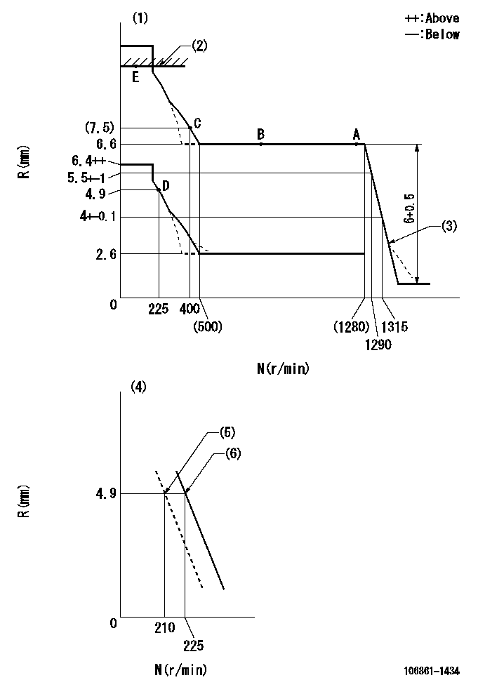
N:Pump speed
R:Rack position (mm)
(1)Tolerance for racks not indicated: +-0.05mm.
(2)RACK LIMIT
(3)Damper spring setting: DL
(4)Variable speed specification: idling adjustment
(5)Main spring setting
(6)Set idle sub-spring
----------
DL=3-0.5mm
----------
----------
DL=3-0.5mm
----------
Speed control lever angle
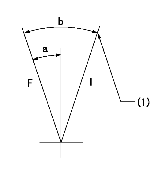
F:Full speed
I:Idle
(1)Stopper bolt setting
----------
----------
a=10deg+-5deg b=(22deg)+-5deg
----------
----------
a=10deg+-5deg b=(22deg)+-5deg
0000000901
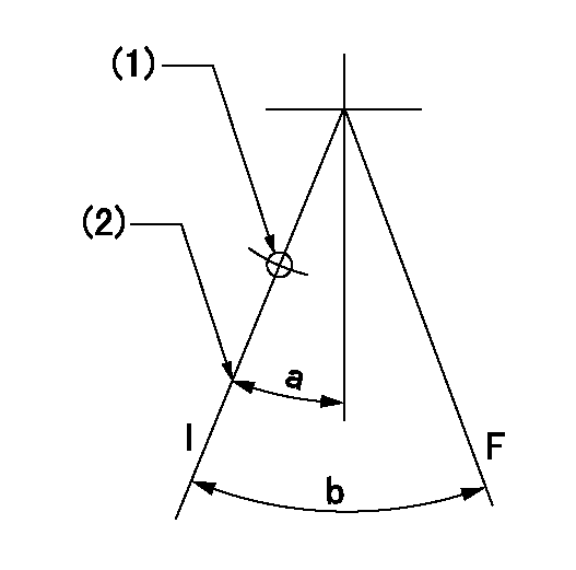
F:Full load
I:Idle
(1)Use the hole at R = aa
(2)Stopper bolt setting
----------
aa=40mm
----------
a=10deg+-5deg b=21.5deg+-3deg
----------
aa=40mm
----------
a=10deg+-5deg b=21.5deg+-3deg
Stop lever angle
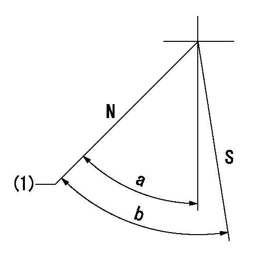
N:Pump normal
S:Stop the pump.
(1)Normal
----------
----------
a=60deg+-5deg b=70deg+-5deg
----------
----------
a=60deg+-5deg b=70deg+-5deg
0000001501 LEVER
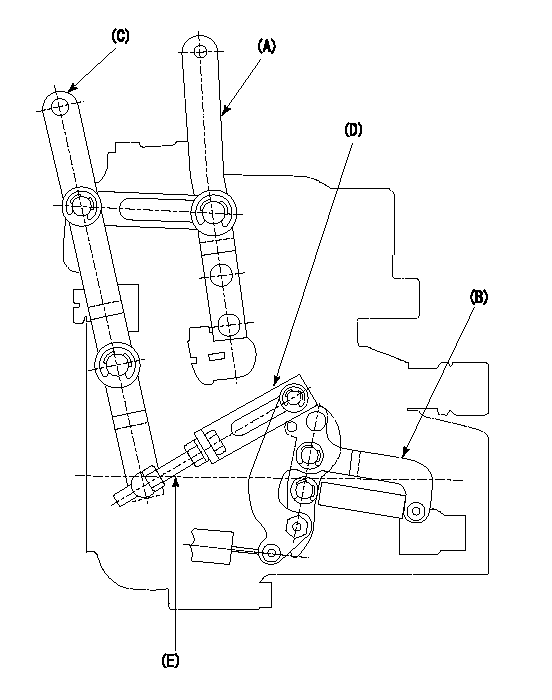
2-stage changeover lever adjustment
(A) Speed lever
(B) Load lever
(C) 2-stage changeover lever
(D) Link
(E) Bolt
1. Minimum-maximum speed specification adjustment (when running)
(1)After completing governor adjustment, hold the 2-stage changeover lever (C) so that the speed lever (A) contacts the full speed stopper.
(2)In this condition, the load lever is held in the idle position.
(3)Adjust bolt (E) so that the clearance between the pin underneath lever (C) and the end of the long groove in link (D) is L.
(4)Lock using the nut.
2. Variable speed specification adjustment (at operation)
(1)Hold the 2-stage changeover lever (C) so that the load lever (B) contacts the full load stopper. (When the load lever is equipped with a cancel mechanism, move it so that it contacts the stopper without canceling.)
(2)In this condition, confirm that the speed lever (A) moves from idle to full speed.
----------
L=1~2mm
----------
----------
L=1~2mm
----------
Timing setting
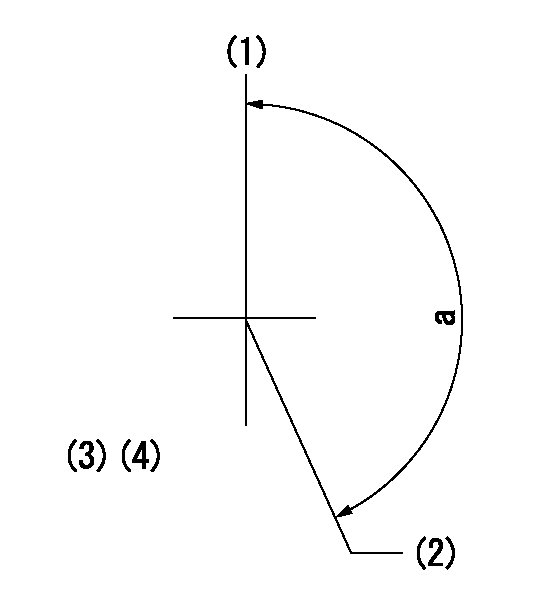
(1)Pump vertical direction
(2)Position of "Z" mark at the No 1 cylinder's beginning of injection (governor side)
(3)B.T.D.C.: aa
(4)-
----------
aa=12deg
----------
a=(170deg)
----------
aa=12deg
----------
a=(170deg)
Information:
TERMINATION DATE
30Sep2015
PROBLEM
The existing 375-5244 or early production 379-0150 common rail fuel injection pumps may fail on certain 336E Excavators. If the existing common rail fuel injection pump fails the engine may exhibit no start, hard starting or loss of power.
AFFECTED PRODUCT
Model Identification Number
336E L BZY00328, 409, 432, 434, 440, 459, 534, 536, 792, 875, 1266, 1319, 1321, 1335
PARTS NEEDED
Qty
Part Number Description
1 6V8260 SEAL-O-RING
1 2287102 SEAL-O-RING-STOR
1 3790150 PUMP GP-FUEL
1 4154991 VALVE AS-RELIEF
1 4286096 KIT-F PUMP LINE
In order to allow equitable parts availability to all participating dealers, please limit your initial parts order to not exceed 32% of dealership population. This is an initial order recommendation only, and the ultimate responsibility for ordering the total number of parts needed to satisfy the program lies with the dealer.
ACTION REQUIRED
1. Refer to Special Instruction, REHS5023, "Replacing the Fuel Injection Pump on Certain C9.3 Engines". Replace the existing 375-5244 or early production 379-0150 common rail fuel injection pump with the new production 379-0150 common rail fuel injection pump and new gasket 6V-8260. Install a new 356-5214 fuel line from the common rail fuel injection pump to the fuel rail.
2. Refer to C9.3 Disassembly and Assembly, KENR8149 "Engines for Caterpillar Built Machines". Replace the prior 362-0770 Pressure Relief Valve with 415-4991 Pressure Relief Valve, and 228-7102 O-ring.
3. Refer to Service Magazine, SEPD1928, "An Improved Fuel Injection Pump Group Is Used on Certain C9.3 Machine Engines", in order to record the common rail fuel injection pump serial number. This serial number must be entered into the containment service letter claim story.
SERVICE CLAIM ALLOWANCES
Product smu/age whichever comes first Caterpillar Dealer Suggested Customer Suggested
Parts % Labor Hrs% Parts % Labor Hrs% Parts % Labor Hrs%
0-5000 hrs,
0-48 mo 100.0% 100.0% 0.0% 0.0% 0.0% 0.0%
This is a 12.0-hour job
PARTS DISPOSITION
Handle the parts in accordance with your Warranty Bulletin on warranty parts handling.
