Information injection-pump assembly
ZEXEL
106861-1326
1068611326
ISUZU
1156017807
1156017807

Rating:
Service parts 106861-1326 INJECTION-PUMP ASSEMBLY:
1.
_
6.
COUPLING PLATE
7.
COUPLING PLATE
8.
_
9.
_
11.
Nozzle and Holder
12.
Open Pre:MPa(Kqf/cm2)
15.7(160)/22.1(225)
15.
NOZZLE SET
Include in #1:
106861-1326
as INJECTION-PUMP ASSEMBLY
Cross reference number
ZEXEL
106861-1326
1068611326
ISUZU
1156017807
1156017807
Zexel num
Bosch num
Firm num
Name
Calibration Data:
Adjustment conditions
Test oil
1404 Test oil ISO4113 or {SAEJ967d}
1404 Test oil ISO4113 or {SAEJ967d}
Test oil temperature
degC
40
40
45
Nozzle and nozzle holder
105780-8140
Bosch type code
EF8511/9A
Nozzle
105780-0000
Bosch type code
DN12SD12T
Nozzle holder
105780-2080
Bosch type code
EF8511/9
Opening pressure
MPa
17.2
Opening pressure
kgf/cm2
175
Injection pipe
Outer diameter - inner diameter - length (mm) mm 8-3-600
Outer diameter - inner diameter - length (mm) mm 8-3-600
Overflow valve (drive side)
134424-3520
Overflow valve opening pressure (drive side)
kPa
255
221
289
Overflow valve opening pressure (drive side)
kgf/cm2
2.6
2.25
2.95
Overflow valve (governor side)
134424-2720
Overflow valve opening pressure (governor side)
kPa
255
221
289
Overflow valve opening pressure (governor side)
kgf/cm2
2.6
2.25
2.95
Tester oil delivery pressure
kPa
157
157
157
Tester oil delivery pressure
kgf/cm2
1.6
1.6
1.6
Direction of rotation (viewed from drive side)
Right R
Right R
Injection timing adjustment
Direction of rotation (viewed from drive side)
Right R
Right R
Injection order
1-8-7-3-
6-5-4-2
Pre-stroke
mm
4
3.97
4.03
Beginning of injection position
Governor side NO.1
Governor side NO.1
Difference between angles 1
Cal 1-8 deg. 45 44.75 45.25
Cal 1-8 deg. 45 44.75 45.25
Difference between angles 2
Cal 1-7 deg. 90 89.75 90.25
Cal 1-7 deg. 90 89.75 90.25
Difference between angles 3
Cal 1-3 deg. 135 134.75 135.25
Cal 1-3 deg. 135 134.75 135.25
Difference between angles 4
Cal 1-6 deg. 180 179.75 180.25
Cal 1-6 deg. 180 179.75 180.25
Difference between angles 5
Cal 1-5 deg. 225 224.75 225.25
Cal 1-5 deg. 225 224.75 225.25
Difference between angles 6
Cal 1-4 deg. 270 269.75 270.25
Cal 1-4 deg. 270 269.75 270.25
Difference between angles 7
Cyl.1-2 deg. 315 314.75 315.25
Cyl.1-2 deg. 315 314.75 315.25
Injection quantity adjustment
Adjusting point
B
Rack position
8.1
Pump speed
r/min
700
700
700
Average injection quantity
mm3/st.
85.6
84.1
87.1
Max. variation between cylinders
%
0
-2
2
Basic
*
Fixing the lever
*
Injection quantity adjustment_02
Adjusting point
C
Rack position
7.9+-0.5
Pump speed
r/min
1250
1250
1250
Average injection quantity
mm3/st.
95.9
91.9
99.9
Max. variation between cylinders
%
0
-3
3
Fixing the lever
*
Injection quantity adjustment_03
Adjusting point
D
Rack position
5.4+-0.5
Pump speed
r/min
225
225
225
Average injection quantity
mm3/st.
8
6.6
9.4
Max. variation between cylinders
%
0
-13
13
Fixing the rack
*
Injection quantity adjustment_04
Adjusting point
F
Rack position
-
Pump speed
r/min
150
150
150
Average injection quantity
mm3/st.
137
137
Fixing the lever
*
Remarks
When manual lever is on the boost side
When manual lever is on the boost side
Injection quantity adjustment_05
Adjusting point
G
Rack position
8.1
Pump speed
r/min
1000
1000
1000
Average injection quantity
mm3/st.
94.8
90.8
98.8
Max. variation between cylinders
%
3
3
3
Fixing the lever
*
Timer adjustment
Pump speed
r/min
-
Advance angle
deg.
0
0
0
Remarks
Measure speed (beginning of operation).
Measure speed (beginning of operation).
Timer adjustment_02
Pump speed
r/min
-
Advance angle
deg.
1
0.5
1
Remarks
Measure the actual speed.
Measure the actual speed.
Timer adjustment_03
Pump speed
r/min
(1075)
Advance angle
deg.
1
0.5
1
Timer adjustment_04
Pump speed
r/min
1150
Advance angle
deg.
3
2.5
3.5
Timer adjustment_05
Pump speed
r/min
1250
Advance angle
deg.
6
5.5
6.5
Remarks
Finish
Finish
Test data Ex:
Governor adjustment
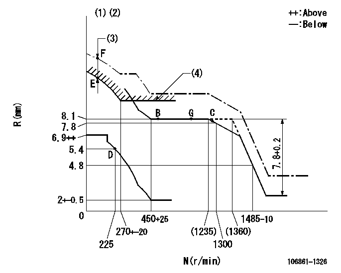
N:Pump speed
R:Rack position (mm)
(1)Supplied with damper spring not set.
(2)Supply solenoid operating voltage DC24V and move the solenoid body so that the excess lever reaches the excess position at the solenoid's maximum stroke.
(3)At excess fuel lever operation: not exceeding EXL
(4)Excess fuel setting for starting: SXL
----------
EXL=2mm SXL=9.2+-0.1mm
----------
----------
EXL=2mm SXL=9.2+-0.1mm
----------
Speed control lever angle

F:Full speed
----------
----------
a=9deg+-5deg
----------
----------
a=9deg+-5deg
0000000901

F:Full load
I:Idle
(1)Stopper bolt setting
(2)Use the hole at R = aa
----------
aa=35mm
----------
a=10deg+-5deg b=33deg+-3deg
----------
aa=35mm
----------
a=10deg+-5deg b=33deg+-3deg
Stop lever angle

N:Pump normal
S:Stop the pump.
----------
----------
a=60deg+-5deg b=73deg+-5deg
----------
----------
a=60deg+-5deg b=73deg+-5deg
0000001101
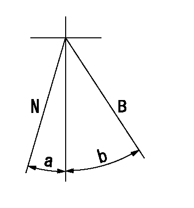
N:Normal
B:When boosted
----------
----------
a=(5deg) b=(24deg)
----------
----------
a=(5deg) b=(24deg)
Timing setting

(1)Pump vertical direction
(2)Position of "Z" mark at the No 1 cylinder's beginning of injection (governor side)
(3)B.T.D.C.: aa
(4)-
----------
aa=12deg
----------
a=(170deg)
----------
aa=12deg
----------
a=(170deg)
Information:
6. Coat the seal of the element with a thin film of clean engine oil or antifreeze. 7. Install the element. Tighten it until the seal contacts the base, then tighten it an additional 3/4 turn. 8. Open the inlet valve and the outlet valve. 9. Maintain the coolant level above the low level plate. 10. Clean and install the radiator cap.11. Start the engine and check for leaks.Brakes
Inspect - Adjust
The machine must be level, the bowl lowered, and the parking brake applied.1. Block the wheels securely.2. Start the engine. 3. When the air pressure reaches the NORMAL range, stop the engine. 4. Release the parking/emergency brake. 5. Measure the distance from the rotochamber to the slack adjuster clevis retaining pin. 6. Apply the service brake and measure the amount of travel of the rod. If the travel is 76 mm (3 inches) or more, adjust the brake.7. Measure the brake rotochamber rod travel of all four wheel brakes. Scraper rotochambers are located inside the push frame.To Adjust
1. Loosen the adjustment locking bolt. 2. Turn the adjusting bolt, as required, until the travel is 41 mm (1.62 inches). 3. Tighten the locking bolt. 4. Apply and release the brakes, watching the rotochamber rod for binding.5. Observe the diaphragm for leaks. 6. Start the engine and allow air pressure to reach 690 kPa (100 psi) or in the green range on the air pressure gauge.7. Apply the parking brake.8. Stop the engine.9. Remove the blocking from the wheels.Check the Air System for Leaks
1. Start the engine and allow air pressure to reach 690 kPa (100 psi) or in the green range on the air pressure gauge. 2. Apply the service brakes and hold them in the applied condition.3. Stop the engine.4. With the brakes applied, watch the air pressure gauge.5. The pressure should drop no more than 35 kPa (5 psi) in 10 minutes.6. If the air pressure loss is greater than 35 kPa (5 psi), inspect the air lines and connections. Make any necessary repairs.To Test Brakes
Be sure the area around the vehicle is clear of personnel and obstructions.Fasten the seat belt before operating the vehicle.Test the brakes on a dry, level surface.
The vehicle must be on a dry, level surface, the bowl lowered and the parking brake applied.The following tests are to determine if the service brake or parking/emergency brake is functional. These tests are not intended to measure maximum brake holding effort.Brake holding effort required to hold a vehicle at a specific engine rpm will vary from vehicle to vehicle due to differences in engine setting, power train efficiency, etc., as well as differences in brake holding ability.Engine rpm at beginning of vehicle movement, with service or parking/emergency brake applied, should be compared against the engine rpm your specific vehicle was able to hold on a prior test, as an indication of system deterioration.Service Brake
1. Start the engine. Allow the engine to reach the normal operating temperature.2. When air pressure registers 690 kPa (100 psi) or