Information injection-pump assembly
ZEXEL
106861-1323
1068611323
Rating:
Service parts 106861-1323 INJECTION-PUMP ASSEMBLY:
1.
_
6.
COUPLING PLATE
7.
COUPLING PLATE
8.
_
9.
_
11.
Nozzle and Holder
1-15300-163-2
12.
Open Pre:MPa(Kqf/cm2)
15.7{160}/22.1{225}

15.
NOZZLE SET
Include in #1:
106861-1323
as INJECTION-PUMP ASSEMBLY
Cross reference number
ZEXEL
106861-1323
1068611323
Zexel num
Bosch num
Firm num
Name
Calibration Data:
Adjustment conditions
Test oil
1404 Test oil ISO4113 or {SAEJ967d}
1404 Test oil ISO4113 or {SAEJ967d}
Test oil temperature
degC
40
40
45
Nozzle and nozzle holder
105780-8140
Bosch type code
EF8511/9A
Nozzle
105780-0000
Bosch type code
DN12SD12T
Nozzle holder
105780-2080
Bosch type code
EF8511/9
Opening pressure
MPa
17.2
Opening pressure
kgf/cm2
175
Injection pipe
Outer diameter - inner diameter - length (mm) mm 8-3-600
Outer diameter - inner diameter - length (mm) mm 8-3-600
Overflow valve (drive side)
134424-3520
Overflow valve opening pressure (drive side)
kPa
255
221
289
Overflow valve opening pressure (drive side)
kgf/cm2
2.6
2.25
2.95
Overflow valve (governor side)
134424-2720
Overflow valve opening pressure (governor side)
kPa
255
221
289
Overflow valve opening pressure (governor side)
kgf/cm2
2.6
2.25
2.95
Tester oil delivery pressure
kPa
157
157
157
Tester oil delivery pressure
kgf/cm2
1.6
1.6
1.6
Direction of rotation (viewed from drive side)
Right R
Right R
Injection timing adjustment
Direction of rotation (viewed from drive side)
Right R
Right R
Injection order
1-8-7-3-
6-5-4-2
Pre-stroke
mm
4
3.97
4.03
Beginning of injection position
Governor side NO.1
Governor side NO.1
Difference between angles 1
Cal 1-8 deg. 45 44.75 45.25
Cal 1-8 deg. 45 44.75 45.25
Difference between angles 2
Cal 1-7 deg. 90 89.75 90.25
Cal 1-7 deg. 90 89.75 90.25
Difference between angles 3
Cal 1-3 deg. 135 134.75 135.25
Cal 1-3 deg. 135 134.75 135.25
Difference between angles 4
Cal 1-6 deg. 180 179.75 180.25
Cal 1-6 deg. 180 179.75 180.25
Difference between angles 5
Cal 1-5 deg. 225 224.75 225.25
Cal 1-5 deg. 225 224.75 225.25
Difference between angles 6
Cal 1-4 deg. 270 269.75 270.25
Cal 1-4 deg. 270 269.75 270.25
Difference between angles 7
Cyl.1-2 deg. 315 314.75 315.25
Cyl.1-2 deg. 315 314.75 315.25
Injection quantity adjustment
Adjusting point
B
Rack position
8.1
Pump speed
r/min
700
700
700
Average injection quantity
mm3/st.
85.6
84.1
87.1
Max. variation between cylinders
%
0
-2
2
Basic
*
Fixing the lever
*
Injection quantity adjustment_02
Adjusting point
C
Rack position
7.9+-0.5
Pump speed
r/min
1250
1250
1250
Average injection quantity
mm3/st.
95.9
91.9
99.9
Max. variation between cylinders
%
0
-3
3
Fixing the lever
*
Injection quantity adjustment_03
Adjusting point
D
Rack position
5.4+-0.5
Pump speed
r/min
225
225
225
Average injection quantity
mm3/st.
8
6.6
9.4
Max. variation between cylinders
%
0
-13
13
Fixing the rack
*
Injection quantity adjustment_04
Adjusting point
F
Rack position
-
Pump speed
r/min
150
150
150
Average injection quantity
mm3/st.
137
137
Fixing the lever
*
Remarks
When manual lever is on the boost side
When manual lever is on the boost side
Timer adjustment
Pump speed
r/min
-
Advance angle
deg.
0
0
0
Remarks
Measure speed (beginning of operation).
Measure speed (beginning of operation).
Timer adjustment_02
Pump speed
r/min
-
Advance angle
deg.
1
0.5
1
Remarks
Measure the actual speed.
Measure the actual speed.
Timer adjustment_03
Pump speed
r/min
(1075)
Advance angle
deg.
1
0.5
1
Timer adjustment_04
Pump speed
r/min
1150
Advance angle
deg.
3
2.5
3.5
Timer adjustment_05
Pump speed
r/min
1250
Advance angle
deg.
6
5.5
6.5
Remarks
Finish
Finish
Test data Ex:
Governor adjustment
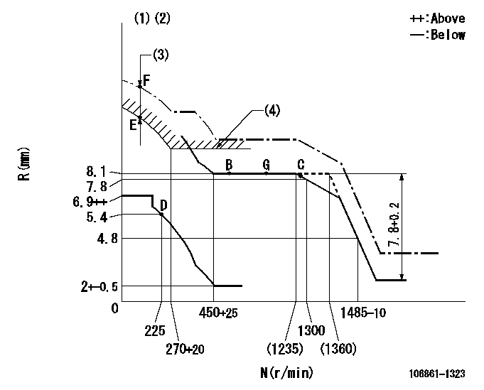
N:Pump speed
R:Rack position (mm)
(1)Supplied with damper spring not set.
(2)Supply solenoid operating voltage DC24V and move the solenoid body so that the excess lever reaches the excess position at the solenoid's maximum stroke.
(3)At excess fuel lever operation: not exceeding EXL
(4)Excess fuel setting for starting: SXL
----------
EXL=2mm SXL=9.2+-0.1mm
----------
----------
EXL=2mm SXL=9.2+-0.1mm
----------
Speed control lever angle

F:Full speed
----------
----------
a=9deg+-5deg
----------
----------
a=9deg+-5deg
0000000901

F:Full load
I:Idle
(1)Stopper bolt setting
(2)Use the hole at R = aa
----------
aa=35mm
----------
a=10deg+-5deg b=33deg+-3deg
----------
aa=35mm
----------
a=10deg+-5deg b=33deg+-3deg
Stop lever angle

N:Pump normal
S:Stop the pump.
----------
----------
a=60deg+-5deg b=73deg+-5deg
----------
----------
a=60deg+-5deg b=73deg+-5deg
0000001101

N:Normal
B:When boosted
----------
----------
a=(5deg) b=(24deg)
----------
----------
a=(5deg) b=(24deg)
Timing setting

(1)Pump vertical direction
(2)Position of "Z" mark at the No 1 cylinder's beginning of injection (governor side)
(3)B.T.D.C.: aa
(4)-
----------
aa=12deg
----------
a=(170deg)
----------
aa=12deg
----------
a=(170deg)
Information:
Fuel Specifications
Types of Fuel
Caterpillar diesel engines have the ability to burn a wide variety of fuels. These fuels are divided into two general groups, preferred and permissible.The preferred fuels provide maximum engine service life and performance. They are distillate fuels. They are commonly called fuel oil, furnace oil, diesel fuel, gas oil or kerosene.The permissible fuels are crude oils or blended fuels. Use of these fuels can result in higher maintenance costs and reduced engine service life.Refer to Fuels for Caterpillar Diesel Engines, Form SEHS7067, for a detailed summary of preferred and permissible fuels and their specifications.Cetane Requirement
The minimum fuel cetane number recommended for the engine is 40.Fuel Cloud Point
Fuel waxing can plug the fuel filters in cold weather. The fuel cloud point must be below the temperature of the surrounding air to prevent filter waxing and power loss. Fuel heating attachments are available from your Caterpillar dealer to minimize fuel filter waxing.Fuel Sulfur Content
The percentage of sulfur in the fuel will affect the engine oil recommendations. If the fuel has over 0.5% sulfur content, the CD engine oil must have a TBN of 20 times the percentage of fuel sulfur (TBN as measured by the ASTM D-2896 method). Your oil supplier should be able to furnish the correct oils.Coolant Specifications
Always use coolant conditioner elements. Never use plain water only.Do not use Caterpillar coolant system conditioner elements with Dowtherm 209 Full-Fill coolant. Follow the instructions provided with the Dowtherm 209 Full-Fill coolant.
Use a mixture of fill water and antifreeze, and a coolant conditioner element.Know Your Cooling System, Form SEBD0518, provides more detailed specifications.Fill Water
Acceptable water for use in the ethylene glycol-type antifreeze and water mixture is shown on the chart below: Antifreeze
Use ethylene glycol-type antifreeze. Use the correct amount to provide freeze protection to the lowest expected outside temperature.Coolant Conditioner Elements
Coolant conditioner elements should be used to maintain a 3% to 6% concentration of conditioner in the coolant. Use a precharge element when filling the complete system, or changing coolant. Install a new maintenance element every 250 service hours during operation. Contact your Caterpillar dealer for the correct coolant conditioner element.Lubricant Specifications
The abbreviations listed below follow S.A.E. J754 nomenclature. The classifications follow S.A.E. J183 classifications. The MIL specifications are U.S.A. Military Specifications. These definitions will be of assistance in purchasing lubricants. The recommended oil viscosities for this machine are found on the "Recommended Lubricant Viscosities" Chart.Engine Oils (CD)
Use oils that meet Engine Service Classification CD (MIL-L-2104C).Consult the EMA Lubricating Oil Data Book, Form SEBU5939, for a listing of CD oil brands.The percentage of sulfur in the fuel will affect the engine oil recommendations. If the fuel has over 0.5% sulfur content, the CD engine oil must have a TBN of 20 times the percentage of fuel sulfur (TBN as measured by the ASTM D-2896 method). Your oil supplier should be able to furnish the correct oils.