Information injection-pump assembly
ZEXEL
106861-1281
1068611281
ISUZU
1156015571
1156015571
Rating:
Service parts 106861-1281 INJECTION-PUMP ASSEMBLY:
1.
_
3.
GOVERNOR
6.
COUPLING PLATE
7.
COUPLING PLATE
8.
_
9.
_
11.
Nozzle and Holder
1-15300-138-2
12.
Open Pre:MPa(Kqf/cm2)
15.7{160}/22.1{225}
15.
NOZZLE SET
Include in #1:
106861-1281
as INJECTION-PUMP ASSEMBLY
Cross reference number
ZEXEL
106861-1281
1068611281
ISUZU
1156015571
1156015571
Zexel num
Bosch num
Firm num
Name
Calibration Data:
Adjustment conditions
Test oil
1404 Test oil ISO4113 or {SAEJ967d}
1404 Test oil ISO4113 or {SAEJ967d}
Test oil temperature
degC
40
40
45
Nozzle and nozzle holder
105780-8140
Bosch type code
EF8511/9A
Nozzle
105780-0000
Bosch type code
DN12SD12T
Nozzle holder
105780-2080
Bosch type code
EF8511/9
Opening pressure
MPa
17.2
Opening pressure
kgf/cm2
175
Injection pipe
Outer diameter - inner diameter - length (mm) mm 8-3-600
Outer diameter - inner diameter - length (mm) mm 8-3-600
Overflow valve opening pressure
kPa
157
123
191
Overflow valve opening pressure
kgf/cm2
1.6
1.25
1.95
Tester oil delivery pressure
kPa
157
157
157
Tester oil delivery pressure
kgf/cm2
1.6
1.6
1.6
Direction of rotation (viewed from drive side)
Right R
Right R
Injection timing adjustment
Direction of rotation (viewed from drive side)
Right R
Right R
Injection order
1-8-7-3-
6-5-4-2
Pre-stroke
mm
4
3.97
4.03
Beginning of injection position
Governor side NO.1
Governor side NO.1
Difference between angles 1
Cal 1-8 deg. 45 44.75 45.25
Cal 1-8 deg. 45 44.75 45.25
Difference between angles 2
Cal 1-7 deg. 90 89.75 90.25
Cal 1-7 deg. 90 89.75 90.25
Difference between angles 3
Cal 1-3 deg. 135 134.75 135.25
Cal 1-3 deg. 135 134.75 135.25
Difference between angles 4
Cal 1-6 deg. 180 179.75 180.25
Cal 1-6 deg. 180 179.75 180.25
Difference between angles 5
Cal 1-5 deg. 225 224.75 225.25
Cal 1-5 deg. 225 224.75 225.25
Difference between angles 6
Cal 1-4 deg. 270 269.75 270.25
Cal 1-4 deg. 270 269.75 270.25
Difference between angles 7
Cyl.1-2 deg. 315 314.75 315.25
Cyl.1-2 deg. 315 314.75 315.25
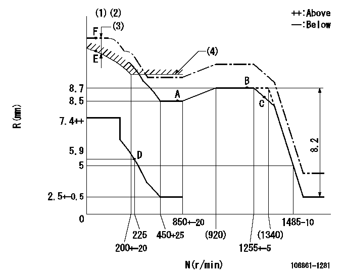
Injection quantity adjustment
Adjusting point
A
Rack position
8.5
Pump speed
r/min
750
750
750
Average injection quantity
mm3/st.
89.8
88.8
90.8
Max. variation between cylinders
%
0
-2
2
Basic
*
Fixing the lever
*
Injection quantity adjustment_02
Adjusting point
B
Rack position
8.7
Pump speed
r/min
1000
1000
1000
Average injection quantity
mm3/st.
105.7
103.7
107.7
Max. variation between cylinders
%
0
-3
3
Fixing the lever
*
Injection quantity adjustment_03
Adjusting point
C
Rack position
8.5+-0.5
Pump speed
r/min
1300
1300
1300
Average injection quantity
mm3/st.
108
104
112
Max. variation between cylinders
%
0
-3
3
Fixing the lever
*
Injection quantity adjustment_04
Adjusting point
D
Rack position
6.8+-0.5
Pump speed
r/min
225
225
225
Average injection quantity
mm3/st.
14.5
13.1
15.9
Max. variation between cylinders
%
0
-13
13
Fixing the rack
*
Remarks
Adjust only variation between cylinders; adjust governor according to governor specifications.
Adjust only variation between cylinders; adjust governor according to governor specifications.
Injection quantity adjustment_05
Adjusting point
F
Rack position
-
Pump speed
r/min
150
150
150
Average injection quantity
mm3/st.
135
135
Fixing the lever
*
Remarks
When manual lever is on the boost side
When manual lever is on the boost side
Test data Ex:
Governor adjustment
N:Pump speed
R:Rack position (mm)
(1)Supplied with damper spring not set.
(2)Supply solenoid operating voltage DC24V and move the solenoid body so that the excess lever reaches the excess position at the solenoid's maximum stroke.
(3)At excess fuel lever operation: not exceeding EXL
(4)Excess fuel setting for starting: SXL
----------
EXL=1.5mm SXL=10.2+-0.1mm
----------
----------
EXL=1.5mm SXL=10.2+-0.1mm
----------
Timer adjustment

(1)Adjusting range
(2)Step response time
(N): Speed of the pump
(L): Load
(theta) Advance angle
(Srd1) Step response time 1
(Srd2) Step response time 2
1. Adjusting conditions for the variable timer
(1)Adjust the clearance between the pickup and the protrusion to L.
----------
L=1-0.2mm N2=800r/min C2=(7.5)deg t1=1.5--sec. t2=1.5--sec.
----------
N1=1100++r/min P1=0kPa(0kgf/cm2) P2=392kPa(4kgf/cm2) C1=7.5+-0.3deg R01=0/4load R02=4/4load
----------
L=1-0.2mm N2=800r/min C2=(7.5)deg t1=1.5--sec. t2=1.5--sec.
----------
N1=1100++r/min P1=0kPa(0kgf/cm2) P2=392kPa(4kgf/cm2) C1=7.5+-0.3deg R01=0/4load R02=4/4load
Speed control lever angle

F:Full speed
----------
----------
a=10deg+-5deg
----------
----------
a=10deg+-5deg
0000000901

F:Full load
I:Idle
(1)Stopper bolt setting
----------
----------
a=10deg+-5deg b=32deg+-3deg
----------
----------
a=10deg+-5deg b=32deg+-3deg
Stop lever angle

N:Pump normal
S:Stop the pump.
----------
----------
a=60deg+-5deg b=73deg+-5deg
----------
----------
a=60deg+-5deg b=73deg+-5deg
0000001101

N:Normal
B:When boosted
----------
----------
a=(5deg) b=(24deg)
----------
----------
a=(5deg) b=(24deg)
0000001501 RACK SENSOR

V1:Supply voltage
V2f:Full side output voltage
V2i:Idle side output voltage
(A) Black
(B) Yellow
(C) Red
(D) Trimmer
(E): Shaft
(F) Nut
(G) Load lever
1. Load sensor adjustment
(1)Connect as shown in the above diagram and apply supply voltage V1.
(2)Hold the load lever (G) against the full side.
(3)Turn the shaft so that the voltage between (A) and (B) is V2.
(4)Hold the load lever (G) against the idle side.
(5)Adjust (D) so that the voltage between (A) and (B) is V2i.
(6)Repeat the above adjustments.
(7)Tighten the nut (F) at the point satisfying the standards.
(8)Hold the load lever against the full side stopper and the idle side stopper.
(9)At this time, confirm that the full side output voltage is V2f and the idle side output voltage is V2i.
----------
V1=5+-0.02V V2f=0.15+0.03V V2i=2.35-0.03V
----------
----------
V1=5+-0.02V V2f=0.15+0.03V V2i=2.35-0.03V
----------
Timing setting

(1)Pump vertical direction
(2)Position of "Z" mark at the No 1 cylinder's beginning of injection (governor side)
(3)B.T.D.C.: aa
(4)-
----------
aa=13deg
----------
a=(170deg)
----------
aa=13deg
----------
a=(170deg)
Information:
Start By:a. remove flywheel The crankshaft rear seal and wear sleeve come as a set and must be installed as a set. If a replacement of the seal is to be made, a replacement of the wear sleeve must also be made. 1. Make at least three holes in seal (1) with a hammer and a sharp punch.2. Use Tool (A) to remove seal (1). 3. Install Tool (C) in the seal bore.4. Install Tool (B) between Tool (C) and wear sleeve (2). Turn Tool (B) until the Tool makes a dent (crease) in wear sleeve (2). Do this in three or more places until the wear sleeve is loose.5. Remove Tools (B) and (C), and remove wear sleeve (2) from the crankshaft.Install Crankshaft Rear Seal & Wear Sleeve
The crankshaft seal and wear sleeve come as a set and must not be separated from each other at any time. Carefully read Special Instruction, SMHS8508, that is included with each seal and wear sleeve before any handling of the seal group is made.
Typical Example1. Install the rear crankshaft seal and wear sleeve with Tool (D). Use the procedures which follow: a. Clean and make a preparation of the wear sleeve inside diameter and crankshaft outside diameter with 6V1541 Quick Cure Primer. Make an application of 9S3265 Retaining Compound to the crankshaft outside diameter before the wear sleeve is installed on the crankshaft. Do not let any Quick Cure Primer or Retaining Compound get on the lip of the seal.b. Install locator (3) and the bolts on crankshaft (4).c. The seal and wear sleeve must be installed dry. Make sure the seal is installed with the part number and the arrows showing crankshaft rotation toward the outside.
The front and rear seals and wear sleeves have different spiral grooves in the seal. Because of this type of design, the rear seal group for an engine is different from the front seal group. If a seal group is installed on the wrong side of the engine, oil can actually be taken out of the engine instead of moving the oil back into the engine.
d. Put wear sleeve (2) and seal (7) as a unit in position on locator (3).e. Put installer (5) in position on locator (3).f. Put clean engine oil on the face of nut (6) and its contact area on installer (5). Install nut (6) on locator (3).g. Tighten nut (6) until installer (5) makes contact with locator (3).h. Remove Tool (D) from the crankshaft seal and wear sleeve. Tool (D) will install the seal and wear sleeve to the correct depth on the crankshaft.End By:a. install flywheel